Do you permit single points of failure in your life?

Wednesday, June 23rd, 2010 by Robert Cravotta

AT&T’s recent national outage of their U-Verse voice service affected me for most of one day last month. Until recently, such outages never affected me because I was still using a traditional landline phone service. That all changed a few months ago when I decided that the risk and consequences of an outage might be offset by the additional services and lower cost of the VoIP service over the landline service. Since the outage, I have been thinking about whether I properly evaluated the risks, costs, and benefits, and whether I should keep or change my services.

The impact of the outage was significant, but not as bad as it could have been. The outage did not affect my ability to receive short phone calls or send and receive emails. It did however severely reduce my ability to make outgoing phone calls and to maintain a long phone call as the calls that did get through would randomly drop. I had one scheduled phone meeting that I had to reschedule as a result of the outage. Overall, the severity and duration of the outage was not sufficient to cause me to drop the VoIP service in favor of the landline service. However, if more similar outages were to occur, say more frequently than on a twelve months cycle or for more than a few hours at a time, I might seriously reconsider this position.

An offsetting factor in this experience was my cell phone. My cell phone sort-of acts as my backup phone in emergencies, but it is insufficient for heavy duty activity in my office because I work at the edge of a wireless dead coverage spot in the mountains. I find it ironic that the cell phone has replaced my landline as my last line of defense to communicate in emergencies because I kept the landline so long as a last line of defense against the wireless phone service going down.

Many people are making this type of trade-off (knowingly or not). A May 12, 2010 report from the Centers for Disease Control and Prevention, says that 24.5% of American homes, in the last half of 2009, had only wireless phones. According to the repost, 48.6% of adults aged 25 to 29 years old lived in households with only wireless phones. The term VoIP never shows up in the report, so I cannot determine whether or not the data lumps landline and VoIP services into the same category.


 100623-phones.png

Going with a wireless only household incurs additional exposures of single point of failure. 9-1-1 operators cannot automatically find you in an emergency. And in a crisis, such as severe storms,

the wireless phone infrastructure may overload and prevent you from receiving a cell signal.

The thing about single points of failure is that they are not always obvious until you are already experiencing the failure. Do you permit single point failures in the way you design your projects or in your personal life choices? For the purpose of this question, ignoring the possibility of a single point failure is an implied acceptance of the risk and benefit trade-off.

If you would like to suggest questions to explore, please contact me at Embedded Insights.

[Editor's Note: This was originally posted on the Embedded Master]

Operational Single Points of Failure

Monday, June 21st, 2010 by Robert Cravotta

A key tenet of fault tolerant designs is to eliminate all single points of failure from the system. A single point of failure is a component or subsystem within a system such that if it suffers a failure, it can cause the rest of the system to fail. When I was first exposed to the single point of failure concept, we used it to refer to sub systems in electronic control systems. A classic example of a single point failure is a function that is implemented completely in software, even if you use multiple functions or algorithms to check each other, because the processor core itself represents a single point of failure in a system with only one processor.

As my experience grew, and I was exposed to more of the issues facing internal program management as well as design level trade-off complexities, I appreciated that single points of failure are not limited to just what is inside your box. It is a system level concept and while it definitely applies to the obvious engineering candidates, such as hardware, software, and mechanical considerations (and thermal and EMI and … and …), it also applies to team processes, procedures, staffing, and even third-party services.

Identifying single points of failure in team processes and procedures can be subtle, but the consequences of allowing them to stay within your system design can be as bad as a normal engineering single point of failure. As an example, processes that only a single person executes are possible sources of failures because there is no cross check or measurement to ensure the person is performing the process correctly and this might allow certain failure conditions to go undetected. In contrast, you can eliminate such a failure point if the process involves more than a single person and the tasks performed by both people support some level of cross-correlation.  

Staffing policies can introduce dangerous single points of failure into your team or company, especially if there is no mechanism for the team to detect and correct when a given skill set is not duplicated across multiple people on the team or in the company. You never know when or why that person with the unique skills or knowledge will become unavailable. While you might be able to contact them if they leave the company or win the lottery, you would have a hard time being able to tap them if they died.

There was a cartoon I displayed in my office for a while many years ago that showed a widow and her child in the rain standing over a grave, and there is an engineer standing next to them asking if the husband ever mentioned anything about source code. The message is powerful and terrifying for anyone that is responsible for maintaining systems. The answer is to plan for redundancy in your staff’s skills and knowledge. When you identify that you have a single point of failure in your staff’s skills or knowledge, commit to fixing that problem as soon as possible. Note that this is a “when condition” and not an “if condition” because it will happen from time to time for reasons completely out of your control.

The thing to remember is that single points of failure can exist anywhere in your system and are not limited to just the components in your products. As systems include more outside or third-party services or partners, the scope of the system grows accordingly and the impact of non-technical single points of failure can grow also.

If you would like to be an information source for this series or provide a guest post, please contact me at Embedded Insights.

[Editor's Note: This was originally posted at the Embedded Master]


Energy Harvesting Sources

Friday, June 18th, 2010 by Robert Cravotta

In my previous post about RF energy harvesting, I focused on a model for intentionally broadcasting RF energy to ensure the ambient energy in the environment was sufficient and consistent enough to power devices on demand that were located in difficult, unsafe, or expensive to reach locations. This approach is the basis for many RFID solutions. Using an intentional model of delivering energy by broadcasting can also simplify the energy harvesting system when the system only needs to operate in the presence of sufficient energy because the device may not need to implement a method of storing and managing the energy during periods of insufficient energy to harvest.

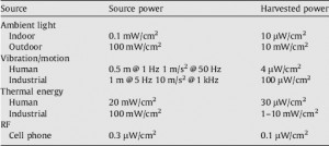
In addition to harvesting RF energy, designers have several options, such as thermal differentials, vibrations, and solar energy for extracting useful amounts of ambient energy. Which type(s) of energy a designer will choose to harness depends significantly on the specific location of the end device within the environment. The table identifies the magnitude of energy that a properly equipped device might expect to extract if placed in the appropriate location. The table also identifies the opportunities of extracting energy from a user by a wearable device. The amount of energy available from a human user is typically two to three orders of magnitude lower than that available in ideal industrial conditions.

Characteristics of ambient and harvested power energy sources (source: imec)

The Micropower Energy Harvesting paper by R.J.M. Vullers, et al., provides a fair amount of detailed information about each type of energy harvesting approach that I summarize here. Solar or photovoltaic harvesters can collect energy from both outdoor and indoor light sources. Harvesting outdoor light offers the highest energy density when the device is being used in direct sun;however, harvesting indoor light can perform comparably with the other forms of energy harvesting listed in the table. Using photovoltaic harvesting indoors requires the use of fine-tuned cellsthat accommodate the different spectral composition of the light and the lower level of illumination than compared to outdoor lighting.

Harvesting energy from motion and vibration may use electrostatic, piezoelectric, or electromagnetic transducers. All vibration-harvesting systems rely on mechanical components that vibrate with a natural frequency close to that of the vibration source, such as a compressor, motor, pump, blowers, or even fans and ducts, to maximize the coupling between the vibration source and the harvesting system. The amount of energy that is extractable from vibrations usually scales with the cube of the vibration frequency and the square of the vibration amplitude.

Harvesting energy with electrostatic transducers relies on a voltage change across a polarized capacitor due to the movement of one moveable electrode. Harvesting energy with piezoelectric transducers relies on motion in the system causing the piezoelectric capacitor to deform which generates a voltage. Harvesting energy with electromagnetic transducers relies on a change in magnetic flux due to the relative motion of a magnetic mass with respect to a coil that generates an AC voltage acrossthe coil.

Harvesting energy from thermal gradients relies on the Seebeck effect where the junction made from two dissimilar conductors causescurrent to flow across the junction when the conductors are different temperatures. A thermopile, a device formed by a large number of thermocouples placed between a hot and cold plate, and which are connected thermally in parallel and electrically in series, is the core element of a thermal energy harvester. The power density of this energy harvesting technique increases as the temperature difference increases.

The majority of these harvesting systems has a relatively large size and is fabricated by standard or fine machining. The advances in research, development, and commercialization of MEMS promise to decrease the cost and increase the energy collection efficiency of energy harvesting devices.

If you would like to be an information source for this series or provide a guest post, please contact me at Embedded Insights.

[Editor's Note: This was originally posted on the Embedded Master]

When is “cutting corners” good engineering versus derelict complacency?

Wednesday, June 16th, 2010 by Robert Cravotta

The recent articles claiming BP was demonstrating carelessness and complacency when the company cut corners in their well design got me thinking. Companies and design teams constantly improve their process in ways that cut costs and shrink schedules. This incremental process of “cutting corners” is the cornerstone of the amazing advances made in technology and improvements in our overall quality of life over the years. There seems to be a lot of second-guessing and criticism by people outside the design, build, and maintenance process when those incremental changes cause a system to cross the line between “good enough” and broken. The disaster that BP is in the middle of right now in the gulf is quite serious, but the magnitude of the disaster makes me think we should explore a thought exercise together.

What would be the cost/benefit if BP never “cut corners” on their well and rig designs? The immediately obvious answer might be, there would be no oil volcano at the bottom of the gulf right now and BP would be happily pumping oil out of that well instead of cleaning up after it. I say volcano because the words spill and leak seem so insufficient to describe the massive force required to spew out all of that oil despite the tremendous pressure pushing down on that opening by being under all of that water. A possible problem with the immediately obvious answer is that it ignores an essential implied assumption. While there might not be any oil pouring into the gulf, we might not be harvesting any of the oil either.

Let’s reword the question to make it more general. What would be the cost to society if everyone only engaged in ventures that would never find the line between good enough and broken? While raising my own children, I developed a sense of the importance that we all need to find the line between good enough and broken. I believe children do not break the rules merely to break the rules – I think they are exploring the edges and refining their own models of what rules are and why and when they should adhere to them. If we deny children the opportunity to understand the edges of rules, they might never develop the understanding necessary to know when to follow and when to challenge a rule.

This concept applies to engineering (as well as any human endeavor). If designers always use large margins in their designs, how will they know when and why they can or should not push those margins? How will they know if the margins are excessive (wasteful) or just right? My experience shows me that people learn the most from the failures, especially because it enables them to refine their models of how and why the world works the way it does.

I think one of the biggest challenges to “cutting corners” is minimizing the impact of when you cross the line to a failure precisely because you do not know where that line is. To me, derelict complacency depends on the assumption that the designer knew where the line to failure was and crossed it anyways. If my engineering career taught me anything, it taught me that we never know what will or will not work until we try it. We can extrapolate from experience, but experience does not provide certainty for everything we have not tried yet.

To an outsider, there might not be an easy to see difference between good engineering and derelict complacency. What are your thoughts on how to describe the difference between appropriate risk-assessed process improvement and derelict complacency? Can we use common failures in the lab to explore, refine, and communicate this difference so that we can apply it to larger disasters such as the oil in the gulf or even unintended acceleration in automobiles?

If you would like to suggest questions to explore, please contact me at Embedded Insights.

[Editor's Note: This was originally posted on the Embedded Master]
Robust Design: Quality vs. Security

Monday, June 14th, 2010 by Robert Cravotta

I had a conversation recently with Nat Hillary, a field application engineer at LDRA Technologies, about examples of software fault tolerance, quality, and security. Our conversation identified many questions and paths that I would like to research further. One such path relates to how software systems that are not fault tolerant may present vulnerabilities that attackers can use to compromise the system. A system’s vulnerability and resistance to software security exploits is generally a specification, design, and implementation quality issue. However, just because secure systems require high quality does not mean that high quality systems are also secure systems because measuring a system’s quality and security focuses on different metrics.


Determining a system’s quality involves measuring and ensuring that each component, separately and together, fits or behaves within some specified range of tolerance. The focus is on whether the system can perform its function with acceptable limits rather than on the complete elimination of all variability. The tightness or looseness of a component’s permitted tolerance balances the cost and difficulty of manufacturing identical components with the cumulative impact of allowing variability among the components against the system’s ability to perform its intended function. For example, many software systems ship with some number of known minor implementation defects (bugs) because the remaining bugs do not prevent the system from operating within tolerances during the expected and likely use scenarios. The software in this case is identical from unit to unit, but the variability in the other components in the system can introduce differences in behavior in the system. I will talk about an exhibit at this year’s ESC San Jose that demonstrated this variability in a future post.


In contrast, a system’s security depends on protecting its vulnerabilities operating under extraordinary conditions. A single vulnerability under the proper extraordinary conditions can compromise the system’s proper operation. However, similar to determining a system’s quality, a system’s security is not completely dependent on a perfect implementation. If the system can isolate and contain vulnerabilities, it can still be good enough to operate in the real world. The 2008 report “Enhancing the Development Life Cycle to Produce Secure Software” identifies that secure software exhibits:


1. Dependability (Correct and Predictable Execution): Justifiable confidence can be attained that software, when executed, functions only as intended;

2. Trustworthiness: No exploitable vulnerabilities or malicious logic exist in the software, either intentionally or unintentionally inserted;

3. Resilience (and Survivability): If compromised, damage to the software will be minimized, and it will recover quickly to an acceptable level of operating capacity;


An example of a software system vulnerability that has a fault tolerant solution is the buffer overflow. The buffer overflow is a technique that exploits functions that do not perform proper bounds checking. The Computer Security Technology Planning Study first publicly documented the technique in 1972. Static analysis software tools are able to assist developers to avoid this type of vulnerability by identifying array overflows and underflows, as well as when signed and unsigned data types are improperly used. Using this fault tolerant approach can allow a software system to exhibit the three secure software properties listed above.

[Editor's Note: This was originally posted on the Embedded Master]

Extreme Processing: Oil Containment Team vs. High-End Multiprocessing

Friday, June 11th, 2010 by Robert Cravotta

Teaser: Extreme processing thresholds do not only apply to the small end of the spectrum – they also apply to the upper end of the spectrum where designers are pushing the processing performance so hard that they are limited by how well the devices and system enclosures are able to dissipate heat. Watching the BP oil well containment effort may offer some possible insights and hints at the direction that extreme high processing systems are headed.

Categories: extreme processing, fault tolerance (redundancy), multiprocessing

Image Caption: “The incident command centre at Houma, Louisiana. Over 2500 people are working on the response operation. © BP p.l.c.”

Extreme Processing: Oil Containment Team vs. High-End Multiprocessing

So far, in this extreme processing series, I have been focusing on the low or small end of the extreme processing spectrum. But extreme processing thresholds do not only apply to the small end of the spectrum – they also apply to the upper end of the spectrum where designers are pushing the processing performance so hard that they are limited by how well the devices and system enclosures are able to dissipate heat. Watching the BP oil well containment effort may offer some possible insights and hints at the direction that extreme high processing systems are headed.

100611-bp-command-center.jpg


According to the BP CEO’s video, there are 17,000 people working on the oil containment team. At a crude level, the containment team is analogous to a 17,000 core multiprocessing system. Now consider that contemporary extreme multiprocessing devices generally offer a dozen or less cores in a single package. Some of the highest density multicore devices contain approximately 200 cores in a single package. The logistics of managing 17,000 distinct team members toward a single set of goals by delivering new information where it is needed as quickly as possible is analogous to the challenges designers of high-end multiprocessing systems face.

The people on the containment team span multiple disciplines, companies, and languages. Even though each team member brings a unique set of skills and knowledge to the team, there is some redundancy in the partitioning of those people. Take for example the 500 people in the crisis center. That group necessarily consists of two or three shifts of people that fulfill the same role in the center because people need to sleep and no single person could operate the center 24 hours a day. A certain amount of redundancy for each type of task the team performs is critical to avoid single-point failures because someone gets sick, hurt, or otherwise becomes unavailable.

Out in the field are many ships directly involved in the containment effort at the surface of the ocean over the leaking oil pipe. Every movement of those ships needs to be carefully planned, checked, and verified by a logistics team before the ships can execute them because those ships are hosting up to a dozen active ROVs (Remotely operated vehicles) that are connected to the ship via mile long cables. Tangling those cables could be disastrous.

In the video, we learn that the planning lead-time for the procedures that the field team executes extends 6 to 12 hours ahead, and some planning extends out approximately a week. The larger, more ambitious projects require even more planning time. What is perhaps understated is that the time frames for these projects is up to four times faster than the normal pace – approximately one week to do what would normally occur in one month of planning.

The 17,000 people are working simultaneously, similar to the many cores in multiprocessing systems. There are people that specialize in routing data and new information to the appropriate groups, analogous to how the scheduling circuits in multiprocessing systems operate. The containment team is executing planning across multiple paths, analogous to speculative execution and multi-pipelining systems. The structure of the team cannot afford the critical path hit of sending all of the information to a central core team to analyze and make decisions – those decisions are made in distributed pockets and the results of those decisions flow to the central core team to ensure decisions from different teams are not exclusive or conflicting with each other.

I see many parallels with the challenges facing designers of multiprocessing systems. How about you? If you would like to be an information source for this series or provide a guest post, please contact me at Embedded Insights.

[Editor's Note: This was originally posted on the Embedded Master]

Question of the Week: Do you always use formal test procedures for your embedded designs?

Wednesday, June 9th, 2010 by Robert Cravotta

I commented earlier this week about how watching the BP oil well capping exercise live video reminded me about building and using formal test procedures when performing complex or dangerous operations. Before I had a lot of experience with test procedures, I used to think of them as an annoying check-off box for quality assurance. They were expensive to make, and they consumed huge amounts of time to build and refine. However, with more experience, I came to appreciate formal test procedures as valuable engineering design tools because they are a mechanism that injects fault tolerance in systems where the operator is an integral part of the system’s decision process. The procedure frees up the operator’s attention while performing “routine tasks” with the system so they can better recognize and react to the shifting external conditions of a complex environment.

Similar to the BP oil well capping exercise, the formal procedures I worked on involved complex systems that used dangerous chemicals. We needed to make sure we did not damage the systems while using them, both for safety and schedule reasons. Building the formal procedure and going through it with the entire team captured each member’s specialized knowledge so that the team was able to develop and refine each step in the procedure with a higher level of confidence than any subset of the team could have performed alone.

I personally understand the value of formal procedures for testing and operating very complex and dangerous systems, but I wonder if the formal procedure process offers similar value, compared to the cost and effort to make one, when applied to simple, low cost, or benign system designs.

Do you always build and use formal test procedures or are there designs that are so simple, low cost, or benign that you skip the process of building a formal test procedure? What types of designs would you consider skipping the formal procedure process and why?

If you would like to suggest questions for future posts, please contact me at Embedded Insights.

[Editor's Note: This was originally posted on the Embedded Master]
Resistive Touch Sensing Primer

Tuesday, June 8th, 2010 by Robert Cravotta

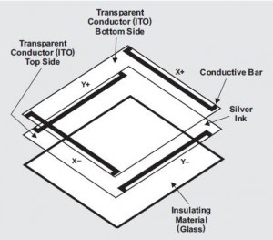
Resistive touch sensors consist of several panels coated with a metallic film, such as ITO (indium tin oxide), which is a transparent and electrically conductive. Thin spacer dots separate the panels from each other. When something, such as a finger (gloved or bare) or a stylus presses on the layers, it causes the two panels to make contact and closes an electrical circuit so that a controller can detect and calculate where the pressure is being applied to the panels. The controller can communicate the position of the pressure point as a coordinate to the application software.

Because the touch sensor relies on pressure on its surface to measure a touch, a user can use any object to make the contact; although using sharp objects can damage the layers. This is in contrast to other types of touch sensors, such as capacitive sensors, which require the object making contact with the touch surface, such as a finger, to be conductive.

Resistive touch sensors are generally durable and less expensive than other touch technologies; this contributes to their wide use in many applications. However, resistive touch sensors offer a lower visual clarity (transmitting about 75% of the display luminance) than other touch technologies. Resistive touch sensors also suffer from a high reflectivity with high ambient light conditions, and this can degrade the perceived contrast ratio of the displayed image.

When a user touches the resistive touch sensor, the top layer of the sensor experiences a mechanical bouncing from the vibration of the pressure. This affects the decay time necessary for the system to reach a stable DC value to determine a position measurement. In addition, affecting the decay time is the parasitic capacitance between the top and bottom layers of the touch sensor, which affect the input of the ADC when the electrode drivers are active.

Resistive touch sensors come in three flavors: 4, 5, and 8 wire interfaces. Four wire configurations offer the lowest cost, but they can require frequent recalibration. The four wire sensor arranges two electrode arrays at opposite sides of the substrate to establish a voltage gradient across the ITO coating. When the user presses the sensor surface, the two sets of electrodes can act together, by alternating the voltage signal between them, to produce a measurable voltage gradient across the substrate. The four wire configuration supports the construction of small and simple touch panels, but they are only rated to survive up to five million touches.

Five wire configurations are more expensive and harder to calibrate, but they improve the sensor’s durability and calibration stability because they use electrodes on all four corners of the bottom layer of the sensor. The top layer acts as a voltage-measuring probe. The additional electrodes make triangulating the touch position more accurate, and this makes it more appropriate for larger, full size displays. Five wire configurations have a higher life span of 35 million touches or more.  

Eight wire configurations derive their design from four wire configurations. The additional four lines (two on each layer) report baseline voltages that enable the controller to correct for drift from ITO coating degradation or from additional electrical resistance the system experiences from harsh environmental conditions. The uses for 8 wire configurations are the same as 4 wire configurations except that 8 wire systems deliver more drift stability over the same period of time. Although the four additional lines stabilize the system against drift, they do not improve the durability or life expectancy of the sensor.

If you would like to participate in this project, post here or email me at Embedded Insights.

[Editor's Note: This was originally posted on Low-Power Design]

Robust Design: Formal Procedures

Monday, June 7th, 2010 by Robert Cravotta

Watching the BP oil pipe-capping live-video the other day made me think about formal procedures. Using a formal procedure is a way to implement the fault tolerant principle in cases where the operator is an integral part of the system’s decision process. Using a formal procedure helps to free up the operator’s attention while performing “routine tasks” so they can better recognize and react to the shifting conditions of a complex environment. Even though I could not see all of the video feeds or hear any of the audio feeds, I could imagine what was going on in each of the feeds during the capping operation.

I have worked on a fair share of path-finding projects that demonstrated the feasibility of many design ideas to make a completely autonomous vehicle that could complete complex tasks in real world environments. The design team would subject new ideas to substantive analysis and review before building a lab implementation that we could test. With each test-case success, we would move closer to testing the system in the target environment (space-based in many cases). One thing that impressed me then and has forever stayed with me is the importance and value of a formal operational procedure document.

I have written and reviewed many operational procedures. When I first started working with these procedures, I thought they were a bother that took a lot of time and effort to produce. We had to explicitly account for and document every little detail that we could imagine, especially the unlikely scenarios that we needed to detect during the system checkouts. We performed what seemed like endless walkthroughs of the procedures – each time refining small details in the procedure as different members of the team would share a concern about this or that. We did the walkthroughs so many times that we could complete them in our sleep. When I finally participated in my first live test, the value of those procedures and all of those walkthroughs became apparent – and they no longer seemed like a waste of time.

The formal procedure was an effective way to capture the knowledge of the many people, each with a different set of skills and specific knowledge about the system, in a single place. By performing all of those walkthroughs, it forced us to consider what we should do under different failure conditions without the burden of having to come up with a solution in real-time. The formal procedure enabled everyone on the team to be able to quickly perform complex and coordinated tasks that would be practically impossible to execute in an impromptu fashion – especially under stressful conditions.

The first and foremost reason for the procedures was to protect the people working around the system. We were dealing with dangerous materials where injuries or deaths were very real possibilities if we were not careful. The second reason for the procedures was to protect the system from operating in a predictable destructive scenario. Unpredictable failures are a common enough occurrence when you are working on the leading (bleeding?) edge because you are working in the realm of the unknown. The systems we were building only existed as a single vehicle or a set of two vehicles, and having to rebuild them would represent a huge setback.

The capping operation of the BP oil-pipe appears to encompass at least as much, if not significantly more, complexity than the projects I worked on so long ago. The video feed showed the ROV (remotely operated vehicle) robot arm disconnecting a blue cable from the capping structure. Then the video feed showed what I interpreted as the ROV operator checking out various points in the system before moving on to the next cable or step in some checklist. I could imagine the numerous go/no-go callouts from each of the relevant team members that preceded each task performed by the ROV operator. I am guessing that the containment team went through a similar process that we went through in building their formal procedures – first in the conference room, then in simulation, and finally on the real thing 5000 feet under the surface of the ocean.

While building and testing prototypes of your embedded systems may not involve the same adrenaline pumping excitement as these two scenarios, the cost of destroying your prototype system can be devastating. If you have experience using formal procedures while building embedded systems, and you would like to contribute your knowledge and experience to this series, please contact me at Embedded Insights.

[Editor's Note: This was originally posted on the Embedded Master]

Extreme Processing: Parallels with an oil leak

Friday, June 4th, 2010 by Robert Cravotta

I took some time today to watch a live video feed of the attempts to cap the BP oil leak. While I was watching the “action”, I realized that this operation demonstrates many extreme concepts that might provide lessons for embedded developers as they continue to push the envelope of what is possible.

The first thing I noticed was the utter lack of light – other than the light from the artificial sources mounted on the ROVs (remotely operated vehicles). The second thing I noticed was the extreme turbulence of the environment – the turbulence is a testament to the magnitude of the raw power of nature. The third thing I noticed was the surreal appearance of calmness, within all of that turbulence, immediately surrounding the structure that the ROVs were manipulating toward the source of the leak.

This operation is taking place 5000 feet below the surface of the ocean – far below the point where sunlight no longer penetrates into the ocean depths (approximately 1000M below the surface). The clarity and details in the video feed belie the challenges that engineers had to solve to provide that much usable light in such a hostile environment.

As processors continue to grow in complexity and on-chip resources, a designer’s ability to see everything that is going on within the processor also grows in complexity. Contemporary processors must be able to collect even more data in an ever-shrinking time window than previous generation devices. Embedded systems that are able to provide real-time data in a continuous stream belie the challenges that chip designers had to solve to provide that much visibility into the chip.

Despite the extreme turbulence around the leak site, the containment team is able to deliberately control and manipulate the equipment into position to attempt to stem the flow from the leak point. The capping structure (my technical term) appears to “gently float” within all of this turbulence in the video feed. I have no doubt that there is a significant amount of equipment and cabling necessary to anchor the equipment so it does not “fly” away. The movements of the ROVs are deliberate, and if you watch long enough, you can discern some “rules” that the ROV operators follow: only grab the white cable with the pinchers; manipulate the blue cables with the white cables or use the robot arm to coax the blue cables to where you need them to go.

Similarly, chip designers of contemporary processors must build their systems to remain resilient despite narrower thresholds for noise and errors. In other words, contemporary devices live in a world of hostile elements in the environment that exhibit an amplified relative magnitude compared to early generation devices. Despite the narrower thresholds, these devices must continue to provide a calm and predictable level of operation that an embedded developer can depend on.

The next post in this series will look at the possible lessons embedded developers might be able to extract from the logistics of this containment effort. If you would like to be an information source for this series or provide a guest post, please contact me at Embedded Insights.

[Editor's Note: This was originally posted on the Embedded Master]