Question of the Week: How much ambiguity does your team permit when assigning a task to a team member?

Wednesday, June 2nd, 2010 by Robert Cravotta

I shared a story a few years back about how when I was a junior member of the technical staff. I learned the value of explicitly allowing some uncertainty in assignments to members of the team. An excerpt from that story illustrates the key point:

The instructions for my lab partner and me were to characterize the camera system and to make sure the automatic-gain-control algorithm appropriately adjusted the camera’s sensitivity. How to test the system remained unspecified. The system engineer had not expected us to try to simulate a single pixel signal. Because we were not influenced by his assumptions about the camera system, we uncovered an anomalous condition in the lab that would have caused the vision system to fail when it was deployed [in low-gravity space].

… A key defining element of engineering is to be able to create systems that can deliver consistent, repeatable, and reliable behavior despite uncertainty and variability over some range of environmental conditions. Dealing with uncertainty is fundamental to being an engineer, and there is usually a positive correlation between the seniority of an engineer and the amount of uncertainty he needs to deal with in his job. It is important to allow some uncertainty to exist in assignments for even the most junior engineers, as it can be a source of growth for them—and it might save a project from failure.

This personal experience made me realize how important it is to provide wiggle room in an assignment, especially to junior members of the team, because it provides a mechanism for them to practice dealing with uncertainty and making guesses. It enables them to practice dealing with increasingly larger amounts of uncertainty as their skill and experience increases. It also helps prepare them for the very real uncertainty that senior members have to deal with when directing new and path-finding projects.

Do you, or does your team lead, allow or make room for ambiguity when assigning a task to a member of your team? Does your team use other methods of encouraging the members to think “outside of the box”? How does your team grow and mentor your junior members?

If you would like to suggest questions for future posts, please contact me at Embedded Insights.

[Editor's Note: This was originally posted on the Embedded Master]

Robust Design: Fault Tolerance – Nature vs. Malicious

Tuesday, June 1st, 2010 by Robert Cravotta

[Editor's Note: This was originally posted on the Embedded Master]

For many applications, the primary focus of robust design principles is on making the design resilient to rare or unexpected real world phenomenon. Embedded designers often employ filters to help mitigate the uncertainty that different types of signal noise can cause. They might use redundant components to mitigate or compensate for specific types of periodic failures within various subsystems. However, as our end devices become ever more connected to each other, there is another source of failure that drives and benefits from a strong set of robust design principles – the malicious attack.

On most of the systems I worked on as an embedded developer, we did not need to spend too much energy addressing malicious attacks on electronics and software within the system because the systems usually included a physical barrier that our electronics control system could safely hide behind. That all changed when we started looking at supporting remote access and control into our embedded subsystems. The project that drove this concept home for me was on a Space Shuttle payload that would repeatedly fire its engines to maneuver around the Shuttle. No previous payload had ever been permitted to fire its engines for multiple maneuvers around the Shuttle before. The only engine fire they performed was to move away from the Shuttle and move into their target orbital position.

The control system for this payload was multiple fault-tolerant, and we often joked among ourselves that the payload would be so safe that it would not ever be able to fire its own engines to perform its tasks because the fault tolerant mechanisms were so complicated. This was even before we knew we had to support one additional type of fault tolerance – ensuring that none of the maneuvering commands came from a malicious source. We had assumed that because we were working in orbital space and the commands would be coming from a Shuttle transmitter, that we were safe from malicious attacks. The NASA engineers were concerned that a ground-based malicious command could send the payload into the Shuttle. The authentication mechanism was crude and clunky by today’s encryption standards. Unfortunately, after more than two years of working on that payload, the program was defunded and we never actually flew the payload around the Shuttle.

Tying this back to embedded systems on the ground, malicious attacks often take advantage of the lack of fault tolerance and security in a system’s hardware and software design. By deliberately injecting fault conditions onto a system or into a communication stream, an attacker with sufficient access to and knowledge of how the embedded system operates, can create physical breaches that provide access to the control electronics or expose vulnerabilities in the software system through techniques such as forcing a buffer overflow.

Adjusting your design to mitigate the consequences of malicious attacks can significantly change how you approach analyzing, building, and testing your system. With this in mind, this series will include topics that would overlap with a series on security issues, but with a mind towards robust design principles and fault tolerance. If you have experience designing for tolerance to malicious attacks in embedded systems, not only with regards to the electronics and software, but also from a mechanical perspective, and you would like to contribute your knowledge and experience to this series, please contact me at Embedded Insights.

Extreme Processing: RF Energy Harvesting

Friday, May 28th, 2010 by Robert Cravotta

[Editor's Note: This was originally posted on the Embedded Master]

In this post I will explore RF energy harvesting – harvesting energy from radio waves. I spoke with Harry Ostaffe, Director of Marketing and Business Development at PowerCast to learn more about RF energy harvesting. Ostaffe informed me of another energy harvesting resource site. The Energy Harvesting Network focuses on disseminating the current and future capabilities of energy harvesting technologies to users in both industry and academia. The site currently lists contact information for 25 academic and 37 industrial members that are involved with energy harvesting.

The effectiveness of energy harvesting depends on the amount and predictable availability of an energy source; whether from radio waves, thermal differentials, solar or light sources, or even vibration sources. There are three categories for ambient energy availability: intentional, anticipated, and unknown. Building a device that powers itself in an environment with unknown and random sources of ambient energy is beyond the scope of this post. If you have experience with these types of designs, please contact me.

100528-energy-sources.jpg

Building a device that relies on anticipated energy sources takes advantage of infrastructure that is already in place in the environment.  For RF systems, this could include scavenging ambient transmissions from cell phones, mobile devices, as well as television and radio broadcasts located in the area. A challenge for systems that rely on anticipated energy sources is that available energy can fluctuate and there is no guarantee that there will be enough energy to scavenge from the environment.

Intentional energy harvesting designs rely on an active component in the system, such as an RF transmitter, that can explicitly provide the desired type of energy into the environment when the device needs it. PowerCast’s approach to support an intentional energy source is to offer a 4W 915 MHz RF transmitter. The intentional energy approach is also appropriate for other types of energy, such as placing an energy harvesting on a piece of industrial equipment that vibrates when it is operating. Another example could involve placing an energy harvesting near a light source that will emit light when the device will be operating and is no longer asleep. Using an intentional energy source allows designers to engineer a consistent energy solution.

An “obvious” frequency sweet spot for RF energy harvesters should be 2.4GHz because so many consumer devices work at that frequency. Ostaffe says that while they have made components that work in the 2.4GHz range, they are currently not publicly available. There is the potential for consumer frustration with a 2.4GHz harvester that currently makes offering harvesters in this frequency range a problematic idea. The first logical spot someone with one of these devices is likely to put them is near their 2.4GHz wireless access point. The problem is that these routers typically transmit in the 100mW range (versus 4W for the 915 MHz transmitter) and that does not provide enough energy for most harvester applications – especially because the energy drops off at 1/r2 from the source. The consumer is likely to attribute the poor performance of the device to a flaw in the device rather than an insufficient power source issue.

If you would like to be an information source for this series or provide a guest post, please contact me at Embedded Insights

Question of the Week: Who is wearing a wristwatch?

Wednesday, May 26th, 2010 by Robert Cravotta

[Editor's Note: This was originally posted on the Embedded Master]

I found my wristwatch the other day, and I realized I have not used it for more than ten years. I originally stopped wearing the watch (and rings) when I suffered from an acute case of tendonitis in my wrists. However, I never went back to wearing a watch on my wrist because I found another way to carry the time and date with me – the humble pocket watch – except this pocket watch also doubles as a mobile phone and offers a slew of other useful functions to boot. This got me wondering, do people still wear wristwatches? Is there a correlation between age of the person and whether they wear a wristwatch? What are the reasons that people do or do not wear wristwatches?

I think the answers to these questions may provide some useful insights to embedded developers about making assumptions. HP’s current plans to complete a prototype of a “Dick Tracy” watch within a year suggest that these questions might not be so silly and frivolous. According to the CNN article, the U.S. military plans to test the prototype with a small group of soldiers; the watch may eliminate the need for soldiers to carry cumbersome gear and backup batteries. The article mentions that the watch will use a plastic display and flexible solar panels.

100526-dick_tracy_watch.jpg

It is not clear that the wristwatch prototype would be able to do anything better than a smart cell phone except that the user can wear it on their wrist instead of somewhere else on their body. Because this watch will be worn on the wrist, the size of the display is necessarily limited; otherwise the watch could become a safety hazard if it is significantly larger than the user’s wrist size. In addition to the constrained display size, there are not a lot of options for providing the user a comprehensive input capability to support the implied sophisticated integrated electronics.

I suspect developing this prototype will cost a large sum of money and engineering resources, and the fact that the money is available for this project makes me wonder if I have underestimated the purported advantage that a wristwatch from factor offers over the form factor flexibility for a cell phone/pocket watch that can be secured to the user in a myriad of ways.

So do you wear a wristwatch? Do you wear one only under certain circumstances? What are your reasons for wearing or not wearing a wristwatch?

If you would like to suggest questions for future posts, please contact me at Embedded Insights.

Microchip mTouch AR1000 Touch Screen Controller

Tuesday, May 25th, 2010 by Robert Cravotta

[Editor's Note: This was originally posted on Low-Power Design]

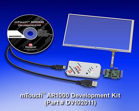
Plans are made to be changed. The first touch development kit I am working with is the Microchip mTouch AR1000 Touch Screen Controller. I did work with the kit on an XP host, but I am delaying writing about the details of the bench exercise because the 64-bit support is scheduled to be available within the next few weeks. I plan to repeat my bench testing with the 64-bit update and combine what I observe with this development kit in a single upcoming post.

The mTouch AR1000 development kit consists of a controller development board, a 7” four-wire resistive touch screen, and a PICkit serial analyzer. I will describe the resistive (as well as capacitive and inductive) touch technology, in a separate post so that I can refer to it in the write-up for any other similar kits. The figure shows the components and the connection points between each of them. The development kit provides power to the sensor and controller through a USB connection with the host. When using this kit, you need to avoid connecting the host USB through a hub to ensure that enough power is supplied to the kit.


The controller is capable of supporting 4-, 5-, and 8-wire resistive touch sensors. The kit includes a 7” four-wire sensor; four-wire sensors represent the largest volume of the resistive touch sensors in the market. I printed the included calibration and POS (point of sale) templates on a piece of paper and placed it under the sensor. The controller board supports SPI and I2C interface connections to send touch sensor data to the embedded target or host processor. The touch data messages consist of pen up, pen down, and an (X, Y) coordinate for a single touch point; if you touch the sensor in more than one location, such as multiple fingers or even your palm, the touch message coordinates will report a single “averaged” location of the touches. The (X, Y) coordinates are auto-scaled across 1024 points along each axis. The controller updates the touch state data as fast as the sensor can support; the included sensor supports 100 to 130 samples per second. The controller provides a first-order filtering of the touch data.

In the next post, I will explain the strengths and trade-offs when using resistive touch sensors followed by a post detailing my experience with this kit on a host running XP and 64-bit operating system. If you would like to participate in this project, post here or email me at Embedded Insights.

Robust Design: Fault Tolerance – Performance vs. Protection

Monday, May 24th, 2010 by Robert Cravotta

[Editor's Note: This was originally posted on the Embedded Master

Fault tolerant design focuses on keeping the system running or safe in spite of failures usually through the use of independent and redundant resources in the system. Implementing redundant resources does not mean that designers must duplicate all of the system components to gain the benefits of a fault tolerant design. To contain the system cost and design complexity, often only the critical subsystems or components are implemented with redundant components. Today we will look at fault tolerance for data storage on long term storage, such as hard disk drives used for network storage to illustrate some of the performance vs. fault tolerance protection trade-offs that designers must make.

As network storage needs continue to grow, the consequences of a hard disk drive failure increase. Hard disk drives are mechanical devices that will eventually fail. As network storage centers increase the number of hard drives in their center, the probability of a drive failure goes up in a corresponding fashion. To avoid loss of data from a hard drive failure, you either must be able to detect and replace the hard drive before it fails, or you must use a fault tolerant approach to compensate for the failure.

Using a RAID (redundant array of independent disks) configuration provides fault tolerance that keeps the data on those drives available and protects it from loss through a single disk drive failure. Using a RAID configuration does not protect the data from application failures or malicious users that cause the data to be overwritten or deleted; regular data backups are a common approach used to protect from those types of failures. RAID is a technique for configuring multiple hard disk drives into a single logical device to increase the data reliability and availability by storing the data redundantly across the drives.

A RAID configuration relies on a combination of up to three techniques: mirroring, striping, and error correction. Mirroring is the easiest method for allocating the redundant data and it consists of writing the same data to more than one disk. This approach can speed up the read speed because the system can read different data from different disks at the same time, but it may trade off write speed if the system must confirm the data is written correctly across all of the drives. Striping is more complicated to implement, and it consists of interlacing the data across more than one disk. This approach permits the system to complete reads and writes faster than performing the same function on a single hard drive. Error correction consists of writing redundant parity data either on a separate disk or striped across multiple disks. Storing the error correction parity data means the amount of usable storage is less than the total amount of raw storage on all of the drives.

The different combinations of these three techniques provide different performance and fault protection trade-offs. A system that implements only data striping (RAID 0) will benefit from faster read performance, but all of the data will be at risk because any disk failure will cause loss of the data in the array. Data recovery can be costly and not guaranteed with this approach. This approach is appropriate for fixed data or program structures, such as operating system images that do not change often and can be recovered by restoring the data image from a backup.

A system that implements only mirroring (RAID 1) creates two identical copies of the data on two different drives; this provides data protection from a drive failure, but it does so at the cost of a 50% storage efficiency because every bit of data is duplicated. This approach allows the system to keep a file system available at all times even when performing backups because it can declare a disk as inactive, perform a backup of that drive, and then rebuild the mirror.

A system that implements data striping across two or more data drives with a dedicated parity drive (RAID 3 and 4) provide better storage efficiency because the fault tolerance is implemented through a single extra drive in the array. The more drives in the array, the higher the storage efficiency. However, all reads and writes access the dedicated parity drive, so the dedicated drive throttles the maximum performance of the system. RAID 5, which stripes the parity data across all of the drives in the array, has all but replaced RAID 3 and 4 implementations.

RAID 5 offers good storage efficiency as the parity data consumes the equivalent of a single drive in the system. This approach suffers from poor write performance because the system must update the parity on each write. Because the parity data is striped across the drives, the system is able to continue degraded (slower) operation despite a hard drive failure. The system is able to rebuild a fault tolerant data image with a new disk drive, such as on a hot swap drive, while the system continues to provide read and write access to the existing data. RAID6 extends on RAID 5 by using additional parity blocks for dual fault tolerance.

Each of these configurations provides different performance and fault tolerance trade-offs and are appropriate based on the context of the subsystem they are used for. Note that a single RAID controller itself can be the single point of failure within a system.

Performance and protection trade-offs are not limited to disk storage. An embedded design might a firmware library from Flash to SRAM to gain a performance boost, but the code in SRAM is now vulnerable to unintended modification. If you would like to participate in a guest post, please contact me at Embedded Insights.

Extreme Processing: New Thresholds of Small

Friday, May 21st, 2010 by Robert Cravotta

[Editor's Note: This was originally posted on the Embedded Master]

While the recent stories about the DNA-based Robot and the Synthetic Organism are not techniques that are available to current embedded developers, I think they point out what type of scale future embedded designs may encompass. In short, the stories relate to building machines that designers can program to perform specific tasks at the molecular or cellular level. Before I relate this to this series, let me offer a quick summary about these two announcements.

The synthetic organism is a synthetic cell that the creators at J. Craig Venter Institute claim is completely controlled by man-made genetic instructions. The new bacterium is solely a demonstration project that tests a technique that may be applied to other bacteria to accomplish specific functions, such as developing microbes that help make gasoline. The bacterium’s genetic code began as a digital computer file, with more than one million base pairs of DNA, which was sent to Blue Heron Bio, a DNA sequencing company, where the file was transformed into hundreds of small pieces of chemical DNA. Yeast and other bacteria were used to assemble the DNA strips into the complete genome, which was transplanted into an emptied cell. The tam claims that the cell can reproduce itself.

100521-dnarobot.jpg

There are two types of DNA-based robots that were announced recently. Each is a DNA walker, also referred to as a molecular spider that move along a flat surface made out of folded DNA, known as DNA origami, that the walker binds and unbinds with to move around. One of the walkers is able to “follow” a path, and there is a video of the route the walker took to get from one point to another. The other type of walker is controlled by single strands of DNA to collect nano-particles.

These two announcements relate to this series both from a size scale perspective and to our current chapter about energy harvesting. The synthetic organism article does not explicitly discuss how the bacterium obtains energy from the environment, but the molecular robot article hints at how the robots harvest energy from the environment.

“The spider is fueled by the chemical interactions its single-stranded DNA “legs” have with the origami surface. In order to take a “step,” the legs first cleave a DNA strand on the surface, weakening its interaction with that part of the origami surface. This encourages the spider to move forward, pulled towards the intact surface, where its interactions are stronger. When the spider binds to a part of the surface that it is unable to cleave, it stops.”

Based on this description, the “programming” is built into the environment and the actual execution of the program is subject to random variability of the molecular material positioning in the surface. Additionally, the energy to enable the robot to move is also embedded in the surface material. This setup is analogous to designing a set of tubes and ruts for water to follow rather than actually programming the robot to make decisions. When our hypothetical water reaches a gravity minimum, it will stop, in a similar fashion to the robot. Interestingly though, in the video, the robot does not actually stop at the end point, it jumps out of the target circle just before the video ends.

I’m not trying to be too critical here; this is exciting stuff. I will try to get more information about the energy and programming models for these cells and robots. If you would like to participate in a guest post, please contact me at Embedded Insights.

Question of the Week: Are universities adequately preparing graduates to enter the embedded engineering workforce?

Friday, May 21st, 2010 by Robert Cravotta

[Editor's Note: This was originally posted on the Embedded Master]

The timing of this question is prompted by a special report (“Hot Careers for College Graduates 2010”) released this Monday by the University of California, San Diego Extension. Of specific interest is the report states that embedded engineering is the fourth hottest career. The report references the Bureau of Labor Statistics figures that predict there will be an additional 295,200 software engineer jobs, an increase of 32 percent, over the 2008 to 2018 decade. I ask whether universities are adequately preparing graduates to enter the embedded engineering market because my own informal and limited survey suggests that many people consider universities as are doing an insufficient job preparing graduates for the embedded community.

The number one hot career in health information technology may offer some insight into this sentiment. According to the report, “Technicians are needed for emerging jobs such as healthcare integration engineer, healthcare systems analyst, clinical IT consultant, and technology support specialist.” While each of these job titles involve competency with computers, the computing skill sets for these types of jobs are completely different than those needed for embedded development. My quick search for university curriculums addressing embedded engineering found a few bachelors, masters, and extension curriculums that appeared to offer appropriate courses.

This question reminds me of how the engineering curriculum changed a few decades ago. My engineering education was broad-based with a strong foundation in all physical sciences. I did not attend my first college programming class until my second year (note: I had already written assemblers, multi-terminal simulators, and database engines in high school). The engineering curriculum morphed from a broad based set of courses to a narrow, discipline-specific set of courses. Freshmen started programming classes in their first year at the expense of not taking any chemistry courses. The curriculum also split CS20 – the 6 unit course that redirected more than two-thirds of the engineering candidates away from computers – into two smaller and easier to digest courses. I often wonder if these changes short-change the freshmen and prolong the day of reckoning for those students that ultimately do not really belong in that curriculum. In my opinion, the killer CS20 route was rough but more humane because it allowed those students that could not cut it to redirect their energy sooner to something they could succeed at without wasting a year on watered down courses.

Even then, I learned embedded development principles on the job, but my educational background left me with enough understanding in the physical sciences that I could quickly understand the new concepts I needed to embrace to build embedded systems.

Is my survey sample biased? Are universities adequately preparing graduates to enter the embedded workforce? Or is the primary burden of growing the next group of embedded developers falling on the shoulders of private industry? And in either case, is that a good or bad thing?

Robust Design: Disposable Design Principle

Wednesday, May 19th, 2010 by Robert Cravotta

[Editor's Note: This was originally posted on the Embedded Master]

The disposable design principle focuses on short life span or limited use issues. At first glance this principle may make you think these principles only apply to cheap systems, but that would be incorrect. An example of an expensive system that can embody the disposable design principle is an expendable vehicle or component such as a rocket engine. These systems are in contrast to a reusable space vehicle, such as the Space Shuttle, which require a heavier mechanical structure and a recovery system, such as wings, thermal protection system and wheels that result in a lower overall payload capacity. In practice, using the single-use systems are less expensive, support a shorter time to launch, and are considered low risk for mission failure for many types of missions, including launching satellites into orbit.

Limited-use or disposable embedded systems can enjoy similar advantages over reusable versions. Limited-use systems are being embedded into all types of applications, such as inventory tracking tags, medical appliances, fireworks, environmental tracking pads for agriculture, security tags on retail items, and authentication modules to ensure that consumable subsystems are not matched with unsupported end-systems.

The disposable design principle also applies to systems that enforce an end-of-life. The plight of CFLs (Compact Fluorescent Lights) is a good example of a product industry that is responding to the consequences of adopting or ignoring the disposable principle. When a CFL reaches its end-of-life, it can manifest a (purportedly) rare failure mode where a fuse on the control board will burn out. I say purportedly rare because every CFL I have used to end-of-life (even on different lamps) has failed the same way with a small fire, smoke that smells like burning plastic, and burnt plastic on the base of the bulb. The CFL industry has taken notice of the consumer concern about unsettling end-of-life behaviors and is setting standards for handling end-of-life for CFLs. Enforcing an end-of-life mechanism can simplify the complexity the designers must accommodate because the system will shut itself down before the probability of key failure modes manifesting crosses some threshold.

Disposable or limited-use does not necessarily mean lower quality of the components, but it can mean that the system can take meaningful optimizations that drastically drop the cost of the system and improve the delivered quality of the end system. Disposable contact lenses are available in many styles, from daily, weekly, and monthly wear. Each type of lens makes different trades in the materials for durability and sterility that allows each to deliver superior quality at each price point.

Disposable hearing aids use a battery or cell that is fitted permanently within the system; there is no way to replace the battery with a new one. Using a permanent battery allows the disposable hearing aid to last longer on the same charge store than traditional hearing aids. The permanent battery also eliminates the need for the designer to implement a battery door and a mechanism for removing and placing batteries into the hearing aid. In fact, some disposable hearing aid designs are able to make use of a larger microphone area that would normally be consumed by a battery replacement door and hinge.

Extreme Processing Thresholds: Energy Harvesting Resources

Monday, May 17th, 2010 by Robert Cravotta

[Editor's Note: This was originally posted at the Embedded Master

For the next few energy harvesting posts, I would like to explore the various approaches for extracting, storing, and using energy from the environment. However, this could take several posts to cover all of this, so I am focusing this post on pointing out various energy harvesting resources for those of you with a need for more information sooner. Let me clarify, by energy harvesting applications, I mean building systems that can extract enough trace amounts of energy from the environment to power their own operation potentially indefinitely. This is in contrast to those efforts to harvesting energy from non-fossil fuel sources as an alternative energy source.

The Energy Harvest Forum is a general site that lists a fair number of companies that claim to be involved in energy harvesting for WSN (Wireless Sensor Network) and control systems. One concern I have about the company links is that they all go to the home page for each company and it is not always obvious how to get to the energy harvesting material at each company’s site. The site lists companies offering piezo, thermal, and photo electric products.

Texas Instruments has an energy harvesting resource at their site that includes information about their parts and development kits that support energy harvesting. The site also includes application notes, whitepapers, videos, and links to articles. Much of the material is company specific, but there is some general information there. At this point, it is one of the few such collections of energy harvesting material available in one place.

In researching this topic, I heard the name of a few companies mentioned by more than one source.  I will try to get more information about each of them, as well as other companies, in follow-up posts. I’m mentioning these companies here because they appear to be active based on mentions from multiple companies that either have or will have energy harvesting resources available later this year. Cymbet’s EnerChip devices provide power storage solutions for applications such as power bridging, permanent power, and wireless sensors. Infinite power Solutions is involved with solid-state, rechargeable thin-film micro-energy storage devices. Powercast is different from the previous two companies in that they focus on delivering micro-power wirelessly via RF energy harvesting.

Micro-energy harvesting seems to be on the cusp of delivering a different way to think about energy for embedded designs. The opportunities for harvesting the trace amounts of energy that is resident in the environment are becoming more compelling as the cost, complexity, and reliability for the energy harvesting approaches continue to evolve toward parity with batteries.