Entries Tagged ‘Touch Screens’

Subtle trade-off complexity

Tuesday, June 29th, 2010 by Robert Cravotta

This project explores the state-of-the-art for touch sensing and development kits from as many touch providers as I can get my hands on. As I engage with more touch providers, I have started to notice an interesting and initially non-obvious set of trade-offs that each company must make to support this project. On the one hand, vendors want to show how well their technology works and how easy it is to use. On the other hand, there are layers of complexity to using touch that means the touch supplier often offers significant engineering field support. Some of the suppliers I am negotiating with have kits they would love to demonstrate for technical reasons, but they are leery of exposing how much designers need domain expertise support to get the system going.

This is causing me to rethink how to highlight the kits. I originally thought I could lay out the good and the ugly from a purely technical perspective, but I am finding out that ugly is context relevant and more subtle than a brief log of working with a kit might justify. Take for example development tools that support 64-bit development hosts – or should I say the lack of such support. More than one touch-sensing supplier does or did not support 64-bit hosts immediately, and almost all of them are on the short schedule path to supporting 64-bit hosts.

As I encounter this lack of what appeared to be an obvious shortfall across more suppliers’ kits, I am beginning to understand that the touch-sensing suppliers have been possibly providing more hands-on support than I first imagined and that this was why they did not have a 64-bit port of their development tools immediately available. To encourage the continued openness of the suppliers, especially for the most exciting products that require the most field engineering support from the supplier, I will try to group common trade-offs that appear among different touch sensing implementations and discuss the context around those trade-offs from a more general engineering perspective rather than as a specific vendor kit issue.

By managing this project in this way, I hope to be able to explore and uncover more of the complexities of integrating touch sensing into your applications without scaring away the suppliers who are pushing the edges of technology from showing off their hottest stuff. If I do this correctly, you will gain a better understanding of how to quickly compare different offerings and identify which trade-offs make the most sense for the application you are trying to build.

[Editor's Note: This was originally posted on Low-Power Design]

Resistive Touch Sensing Primer

Tuesday, June 8th, 2010 by Robert Cravotta

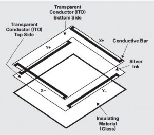
Resistive touch sensors consist of several panels coated with a metallic film, such as ITO (indium tin oxide), which is a transparent and electrically conductive. Thin spacer dots separate the panels from each other. When something, such as a finger (gloved or bare) or a stylus presses on the layers, it causes the two panels to make contact and closes an electrical circuit so that a controller can detect and calculate where the pressure is being applied to the panels. The controller can communicate the position of the pressure point as a coordinate to the application software.

Because the touch sensor relies on pressure on its surface to measure a touch, a user can use any object to make the contact; although using sharp objects can damage the layers. This is in contrast to other types of touch sensors, such as capacitive sensors, which require the object making contact with the touch surface, such as a finger, to be conductive.

Resistive touch sensors are generally durable and less expensive than other touch technologies; this contributes to their wide use in many applications. However, resistive touch sensors offer a lower visual clarity (transmitting about 75% of the display luminance) than other touch technologies. Resistive touch sensors also suffer from a high reflectivity with high ambient light conditions, and this can degrade the perceived contrast ratio of the displayed image.

When a user touches the resistive touch sensor, the top layer of the sensor experiences a mechanical bouncing from the vibration of the pressure. This affects the decay time necessary for the system to reach a stable DC value to determine a position measurement. In addition, affecting the decay time is the parasitic capacitance between the top and bottom layers of the touch sensor, which affect the input of the ADC when the electrode drivers are active.

Resistive touch sensors come in three flavors: 4, 5, and 8 wire interfaces. Four wire configurations offer the lowest cost, but they can require frequent recalibration. The four wire sensor arranges two electrode arrays at opposite sides of the substrate to establish a voltage gradient across the ITO coating. When the user presses the sensor surface, the two sets of electrodes can act together, by alternating the voltage signal between them, to produce a measurable voltage gradient across the substrate. The four wire configuration supports the construction of small and simple touch panels, but they are only rated to survive up to five million touches.

Five wire configurations are more expensive and harder to calibrate, but they improve the sensor’s durability and calibration stability because they use electrodes on all four corners of the bottom layer of the sensor. The top layer acts as a voltage-measuring probe. The additional electrodes make triangulating the touch position more accurate, and this makes it more appropriate for larger, full size displays. Five wire configurations have a higher life span of 35 million touches or more.  

Eight wire configurations derive their design from four wire configurations. The additional four lines (two on each layer) report baseline voltages that enable the controller to correct for drift from ITO coating degradation or from additional electrical resistance the system experiences from harsh environmental conditions. The uses for 8 wire configurations are the same as 4 wire configurations except that 8 wire systems deliver more drift stability over the same period of time. Although the four additional lines stabilize the system against drift, they do not improve the durability or life expectancy of the sensor.

If you would like to participate in this project, post here or email me at Embedded Insights.

[Editor's Note: This was originally posted on Low-Power Design]
Microchip mTouch AR1000 Touch Screen Controller

Tuesday, May 25th, 2010 by Robert Cravotta

[Editor's Note: This was originally posted on Low-Power Design]
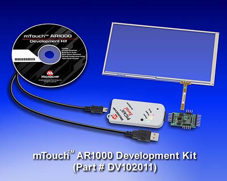
Plans are made to be changed. The first touch development kit I am working with is the Microchip mTouch AR1000 Touch Screen Controller. I did work with the kit on an XP host, but I am delaying writing about the details of the bench exercise because the 64-bit support is scheduled to be available within the next few weeks. I plan to repeat my bench testing with the 64-bit update and combine what I observe with this development kit in a single upcoming post.

The mTouch AR1000 development kit consists of a controller development board, a 7” four-wire resistive touch screen, and a PICkit serial analyzer. I will describe the resistive (as well as capacitive and inductive) touch technology, in a separate post so that I can refer to it in the write-up for any other similar kits. The figure shows the components and the connection points between each of them. The development kit provides power to the sensor and controller through a USB connection with the host. When using this kit, you need to avoid connecting the host USB through a hub to ensure that enough power is supplied to the kit.


The controller is capable of supporting 4-, 5-, and 8-wire resistive touch sensors. The kit includes a 7” four-wire sensor; four-wire sensors represent the largest volume of the resistive touch sensors in the market. I printed the included calibration and POS (point of sale) templates on a piece of paper and placed it under the sensor. The controller board supports SPI and I2C interface connections to send touch sensor data to the embedded target or host processor. The touch data messages consist of pen up, pen down, and an (X, Y) coordinate for a single touch point; if you touch the sensor in more than one location, such as multiple fingers or even your palm, the touch message coordinates will report a single “averaged” location of the touches. The (X, Y) coordinates are auto-scaled across 1024 points along each axis. The controller updates the touch state data as fast as the sensor can support; the included sensor supports 100 to 130 samples per second. The controller provides a first-order filtering of the touch data.

In the next post, I will explain the strengths and trade-offs when using resistive touch sensors followed by a post detailing my experience with this kit on a host running XP and 64-bit operating system. If you would like to participate in this project, post here or email me at Embedded Insights.

User Interfaces: Test Bench and Process for Projects

Tuesday, May 11th, 2010 by Robert Cravotta

[Editor's Note: This was originally posted on Low-Power Design

To avoid confusion or the need for repetitious information in later posts, I will now describe the test bench and process I am using for these touch development kit projects. This process is something I have refined over a number of previous hands-on projects that involved using embedded resources from multiple vendors. The goal of the process is to extract the most value from the effort while minimizing the time spent dealing with the inevitable usability issues that arise when working with so many different kits.

I have several goals when I perform this kind of hands-on project. First and foremost, I want to understand the state-of-the-art for touch development kits. Each company is serving this market from a slightly different angle, and their board and software support reflects different design trade-offs. I believe uncovering those trade-offs will provide you with better insight into how each kit can best meet your needs in your own touch projects.

Additionally, each company is at a different point of maturity in supporting touch. Some companies are focusing on providing the best signal-to-noise ratio at the sensor level and the supported software abstractions may require you to become an expert in the sensor’s idiosyncrasies to extract that next new differentiating feature. Likewise, the company may focus on simplifying the learning curve to implement touch in your design; the software may abstract more of the noise filtering and allow/limit you to treating touch as a simple on/off switch or an abstracted mouse pointer. Or the company’s development kit may focus on providing rich filtering capabilities while still allowing you to work with the raw signals for truly innovative features. My experience suggests the kits will run the entire gamut of maturity and abstraction levels.

Another goal is to help each company that participates in this project to improve their offering. One way to do this is to work with an application engineer from the company that understands the development kit we will be working with. Working with the application engineer not only permits the company to present their development kit’s capabilities in the best possible light and enables me to complete the project more quickly, but it puts the kit through a set of paces that invariably causes something to not work as expected. This helps the application engineer to gain a new understanding of how the touch kit can be used by a developer and that results in direct feedback to the development team and spawns a refinement that improves the kit for the entire community. This is especially relevant because many of the kits will have early adopter components – software modules that are “hot off the press” and may not have completely gone through the field validation process yet. This exercise becomes a classic developer and user integration effort that is the embedded equivalent to dogfooding (using you own product).

In addition to the development boards and software that is included in each touch development kit, I will be using a Dell Inspiron 15 laptop computer running Windows 7 Home Premium (64-bit) for the host development system. One reason I am using this laptop is to see how well these development kits support the Windows 7 environment. Experience suggests that at least one kit will have issues that will be solved by downloading or editing a file that is missing from the production installation files.

So in short, I will be installing the development software on a clean host system that is running Windows 7. I will be spending a few hours with an application engineer, either over the phone or face-to-face, as we step through installing the development software, bringing-up and verifying the board is operating properly from the factory, loading a known example test program, building a demonstration application, and doing some impromptu tweaks to the demonstration application to find the edges of the system’s capabilities. From there, I will post about the experience with a focus on what types of problem spaces the development kit is best suited for, and what opportunities you may have to add new differentiating capabilities to your own touch applications.

If you would like to participate in this project post here or email me at Embedded Insights.

User Interfaces: First Project

Tuesday, April 27th, 2010 by Robert Cravotta

[Editor's Note: This was originally posted on Low-Power Design

To launch the HMI (human-machine interface) development tool projects, I will be focusing my efforts on exploring development kits along with their accompanying software tools and APIs (application programming interface) for touch interfaces. This project includes addressing button and touch screen form factors. Microchip has graciously volunteered their mTouch development kits for the first project. We are currently in the logistics planning phase. At this time, the proposal consists of two example projects.

The first example project focuses on touch button designs by using the mTouch Capacitive Touch Evaluation Kit (part # DM183026) to develop a six (or more)-button board based on a “custom” shape and size for a typical end design. The kit contains one 16-bit and two 8-bit mother boards, based on the PIC24F, PIC16F, and PIC18F, and four daughter boards that support 8 keys, 12 matrixed keys, a 100 point slider, and a 255 point slider. The kit also includes the PICkit Serial Analyzer to connect to the PC Host for the MPLAB mTouch Diagnostic Tool Plug-In software. The goal of this kit is demonstrate the function-specific daughter boards.

The second example project ups the development complexity by focusing on a touch screen design by using the mTouch AR1000 Development Kit (part # DV102011) to configure, calibrate and test an 8-wire analog resistive touch screen. The kit includes a 7 four-wire resistive touch screen and a PICkit Serial Analyzer. The development board has 4-, 5-, and 8-wire headers to connect to a touch screen for testing, and the kit includes adapter cables to support the various pinouts common for resistive touch screens.

I will be completing these projects on my own equipment to ensure the effort is based on a realistic out of the box experience. I look forward to sharing my experience and thoughts about these two development kits in follow up posts in the near future.

Which touch development kit would you like me to work with after the Microchip effort? Please continue to suggest vendors and development kits you would like me to explore in this series by posting here or emailing me at Embedded Insights.

User Interfaces: Introduction

Tuesday, April 13th, 2010 by Robert Cravotta

[Editor's Note: This was originally posted on Low-Power Design

The pursuit of better user interfaces constantly spawns new innovative ideas to make it easier for a user to correctly, consistently, and unambiguously direct the behavior of a machine. For this series, I propose to explore logical and direct as two user interface categories. Both categories are complex enough to warrant a full discussion on their own.

I define logical user interfaces as the subsystems that manage those signals and feedbacks that exist within the digital world of software after real-world filtering. Logical user interfaces focus on the ease of teaching/learning communication mechanisms, especially via feedbacks, between user and machine to enable the user to quickly, accurately, and intuitively control a system as they intend to with a minimum of stumbling to find the way to tell the system what the user wants it to do.

I define direct user interfaces as the subsystems that collect real-world signals at the point where user and machine directly interface with one another. For a keyboard, this would include the physical key switches. For mouse-based interfaces, this would include the actual mouse mechanism, including buttons, wheels, and position sensing components. For touch interfaces, this would include the touch surface and sensing mechanisms. For direct user interface subsystems, recognizing and filtering real-world noise is an essential task.

A constant challenge for direct user interfaces is how to accurately infer a user’s true intent in a noisy world. Jack Ganssle’s “Guide to Debouncing” is a good indication of the complexity that designers still must tame to manage the variable, real-world behavior of a simple mechanical switch with the user’s expectations for simple and accurate operation when the user toggles a switch to communicate with the system.

As systems employ more complex interface components than mere switches, the amount of real-world input variability these systems must accommodate increases. This is especially true for the rapidly evolving types of user interfaces that include touch screens and speech recognition. Similar to the debounce example, these types of interfaces are relying on increasing amounts of software processing to better distinguish real-world signal from real-world noise.

To begin this series, I will be focusing mostly on the latter category of direct user interfaces. I believe understanding the challenges to extract user intent from within a sea of real-world noise is essential to discuss how to address the types of ambiguity and uncertainty logical user interfaces are subject to. Another reason to start with direct user interfaces is because over the previous year there has been an explosion of semiconductor companies that have introduced, expanded, or evolved their touch interface offerings.

To encourage a wider range of developers to adopt their touch interface solutions, these companies are offering software development ecosystems around their mechanical and electrical technologies to make it easier for developers to add touch interfaces to their designs. This is the perfect time to examine their touch technologies and evaluate the maturity of their surrounding development ecosystems. I also propose to explore speech recognition development kits in a similar fashion.

Please help me identify touch and speech recognition development kits to try out and report back to you here. My list of companies to approach for touch development kits includes (in alphabetical order) Atmel, Cypress, Freescale, Microchip, Silicon Labs, Synaptics, and Texas Instruments. I plan to explore touch buttons and touch screen projects for the development kits; companies that support both will have the option to support one or both types of project.

My list of companies to approach for speech recognition development kits includes (in alphabetical order) Microsoft, Sensory, and Tigal. I have not scoped the details for a project with these kits just yet, so if you have a suggestion, please share.

Please help me prioritize which development kits you would like to see first. Your responses here or via email will help me to demonstrate to the semiconductor companies how much interest you have in their development kits.

Please suggest vendors and development kits you would like me to explore first in this series by posting here or emailing me at Embedded Insights.