Over the past few years, electronic ink has been showing up in an increasing number of end-user products. Approximately ten years ago, there were a couple of competing approaches to implementing electronic ink, but E-Ink’s approach has found the most visible success of moving from the lab and viably existing in production level products, such as e-readers, indicators for USB sticks or batteries, as well as watch, smart card, and retail signage displays.
As a display technology, electronic ink exhibits characteristics that distinguish it from active display technologies. The most visible difference is that electronic ink exhibits the same optical characteristics as the printed page. Electronic ink displays do not require back or front lights; rather, they rely on reflecting ambient light with a minimum of 40% reflectivity. This optical quality contributes to a wider viewing angle (almost 180 degrees), better readability over a larger range of lighting conditions (including direct sunlight), and lower energy consumption because the only energy consumed by the display is to change the state of each pixel. Once an image is built on a display, it will remain there until there is another electrical field applied to the display – no energy is consumed to maintain the image. The switching voltage is designed around +/- 15 V.
However, electronic ink is not ideal for every type of display. The 1 to 10 Hz refresh rate is too slow for video. Until recently, electronic ink displays only supported up to 16 levels of grey scale monochrome text and images. The newest electronic ink displays now support up to 4096 colors (with 4-bit CR bias) along with the 16 levels of grey scale. Interestingly, adding support for color does not fundamentally change the approached used to display monochrome images.
The pigments and the chemistry are exactly the same between monochrome and color display; however, the display structure itself is different. The display is thinner so that it can be closer to a touch sensor to minimize parallax error that can occur based on the thickness of the glass over the display (such as with an LCD). Additionally, the display adds a color filter layer on the display and refines the process for manipulating the particles within each microcapsule.

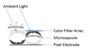
The positively charged white particles reflect light while the negatively charged black particles absorb light.
The 1.2 mm thick electronic ink display consists of a pixel electrode layer, a layer of microcapsules, and a color filter array (Figure 1). The electrode layer enables the system to attract and repel the charged particles within each of the microcapsules to a resolution that exceeds 200 DPI (dots per inch). Within each microcapsule are positively charged white particles and negatively charged black particles which are all suspended within a clear viscous fluid. When the electrode layer applies a positive or negative electric field near each microcapsule, the charged particles within it move to the front or back of the microcapsule depending on whether it is attracted or repelled from the electrode layer.

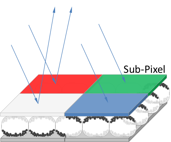
The color filter array consists of a red, green, blue, and white sub-pixel segment at each pixel location. Controlling the absorption or reflection of light at each segment yields 4096 different color combinations.
This display uses an RGBW (Red, Green, Blue, and White) color system that delivers a minimum contrast ratio of 10:1 (Figure 2). For example, to show red, you would bring the white particles forward in the microcapsules under the red segment of the filter array while bringing the black particles forward in the other segments of the array. To present a brighter red color, you can also bring the white particles forward under the white segment of the filter array – however, the color will appear less saturated. To present a black image, the black particles are brought forward under all of the color segments. To present a white image, the white particles are brought forward under all of the color segments because under the RGBW color system, white is the result of all of the colors mixed together.
As electronic ink technology continues to mature and find a home in more applications, I expect that we will see developers take advantage of the fact that these types of displays can be formed into any shape and can be bent without damaging them. The fact that the color displays rely on the same chemistry as the monochrome ones suggests that adding color to a monochrome-based application should not represent a huge barrier to implement. However, the big challenge limiting where electronic ink displays can be used is how to implement the electrode layer such that it still delivers good enough resolution in whatever the final shape or shapes the display must support.
