Entries Tagged ‘Color Display’

Touch with the Microsoft Surface 2.0

Tuesday, March 29th, 2011 by Robert Cravotta

The new Microsoft Surface 2.0 will become available to the public later this year. The technology has undergone significant changes from when the first version was introduced in 2007. The most obvious change is that the dimensions of the newer unitis much thinner, so much so, that the 4 inch thick display can be wall mounted – effectively enabling the display to act like a large-screen 1080p television with touch capability.Not only is the new display thinner, but the list price has nearly halved to $7600. While the current production versions of the Surface are impractical for embedded developers, the sensing technology is quite different from other touch technologies and may represent another approach to user touch interfaces that will compete with other forms of touch technology.

Namely, the touch sensing in the Surface is not really based on sensing touch directly – rather, it is based on using IR (infrared) sensors the visually sense what is happening around the touch surface. This enables the system to sense and be able to interact with nearly any real world object, not just conductive surfaces such as with capacitive touch sensing or physical pressure such as with resistive touch sensing. For example, there are sample applications of the Surface working with a real paint brush (without paint on it). The system is able to identify objects with identification markings, in the form of a pattern of small bumps, to track those objects and infer additional information about them that other touch sensing technologies currently cannot do.
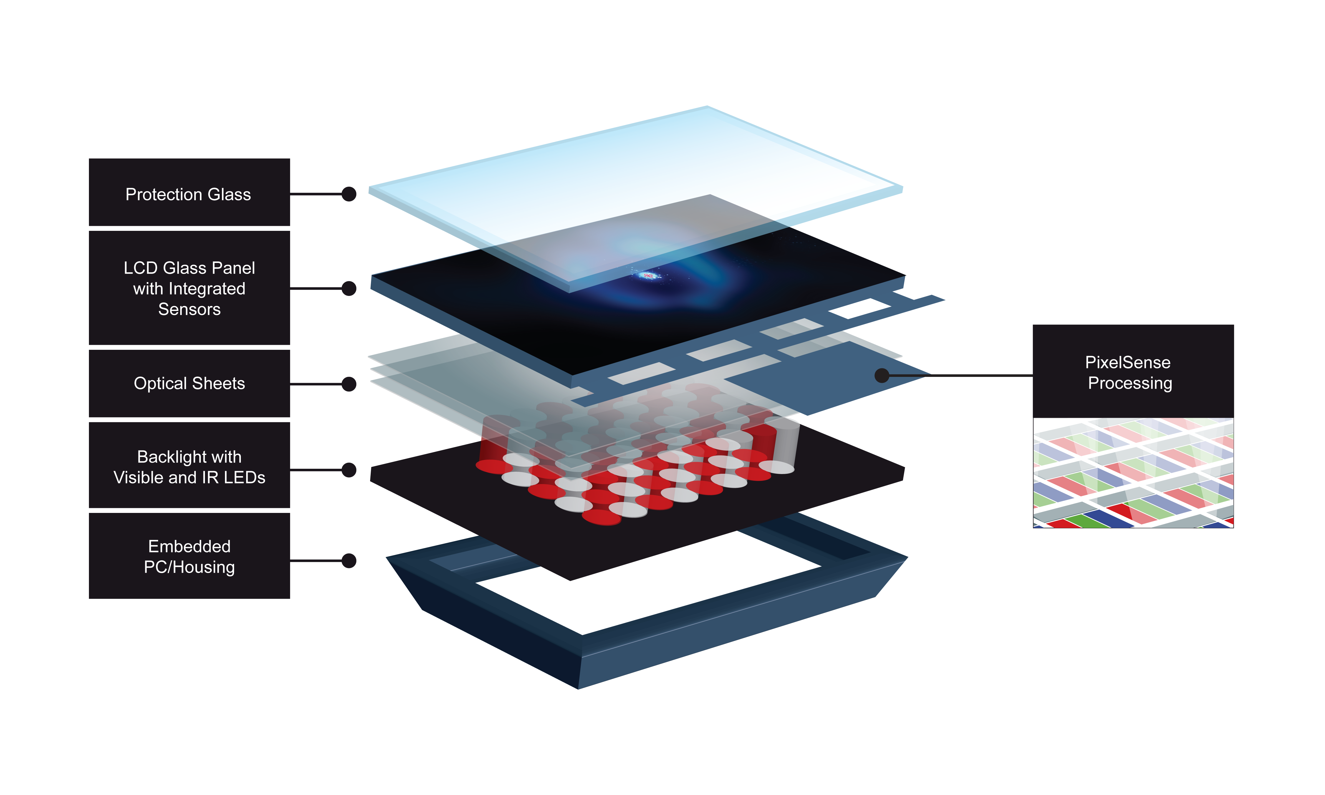
This exploded view of the Microsoft Surface illustrate the various layers that make up the display and sensing housing of the end units. The PixelSense technology is embedded into the LCD layers of the display.

The vision sensing technology is called PixelSense Technology, and it is able to sense the outlines of objects that are near the touch surface and distinguish when they are touching the surface. Note: I would include a link to the PixelSense Technology at Microsoft, but it is not available at this time. The PixelSense Technology embedded in the Samsung SUR40 for Microsoft Surface replaces the five (5) infrared cameras that the earlier version relies on. The SUR40 for Microsoft Surface is the result of a collaborative development effort between Samsung and Microsoft. Combining the Samsung SUR40 with Microsoft’s Surface Software enables the entire display to act as a single aggregate of pixel-based sensors that are tightly integrated with the display circuitry. This shift to an integrated sensor enables the finished casing to be substantially thinner than previous versions of the Surface.

The figure highlights the different layers that make up the display and sensing technology. The layers are analogous to any LCD display except that the PixelSense sensors are embedded in the LCD layer and do not affect the original display quality. The optical sheets include material characteristics to increase the viewing angle and to enhance the IR light transmissivity. PixelSense relies on the IR light generated at the backlight layer to detect reflections from objects above and on the protection layer. The sensors are located below the protection layer.

The Surface software targets an embedded AMD Athlon II X2 Dual-Core Processor operating at 2.9GHz and paired with an AMD Radeon HD 6700M Series GPU using DirectX 11 acting as the vision processor. Applications use an API (application program interface) to access the algorithms contained within the embedded vision processor. In the demonstration that I saw of the Surface, the system fed the IR sensing to a display where I could see my hand and objects above the protection layer. The difference between an object hovering over and touching the protection layer is quite obvious. The sensor and embedded vision software are able to detect and track more than 50 simultaneous touches. Supporting the large number of touches is necessary because the use case for the Surface is to have multiple people issuing gestures to the touch system at the same time.

This technology offers exciting capabilities for end-user applications, but it is currently not appropriate, nor available, for general embedded designs. However, as the technology continues to evolve, the price should continue to drop and the vision algorithms should mature so that they can operate more efficiently with less compute performance required of the vision processors (most likely due to specialized hardware accelerators for vision processing). The ability to be able to recognize and work with real world objects is a compelling capability that the current touch technologies lack and may never acquire. While the Microsoft person I spoke with says the company is not looking at bringing this technology to applications outside the fully integrated Surface package, I believe the technology will become more compelling for embedded applications sooner rather than later. At that point, experience with vision processing (different from image processing) will become a valuable skillset.

How to add color to electronic ink

Tuesday, February 15th, 2011 by Robert Cravotta

Over the past few years, electronic ink has been showing up in an increasing number of end-user products. Approximately ten years ago, there were a couple of competing approaches to implementing electronic ink, but E-Ink’s approach has found the most visible success of moving from the lab and viably existing in production level products, such as e-readers, indicators for USB sticks or batteries, as well as watch, smart card, and retail signage displays.

As a display technology, electronic ink exhibits characteristics that distinguish it from active display technologies. The most visible difference is that electronic ink exhibits the same optical characteristics as the printed page. Electronic ink displays do not require back or front lights; rather, they rely on reflecting ambient light with a minimum of 40% reflectivity. This optical quality contributes to a wider viewing angle (almost 180 degrees), better readability over a larger range of lighting conditions (including direct sunlight), and lower energy consumption because the only energy consumed by the display is to change the state of each pixel. Once an image is built on a display, it will remain there until there is another electrical field applied to the display – no energy is consumed to maintain the image. The switching voltage is designed around +/- 15 V.

However, electronic ink is not ideal for every type of display. The 1 to 10 Hz refresh rate is too slow for video. Until recently, electronic ink displays only supported up to 16 levels of grey scale monochrome text and images. The newest electronic ink displays now support up to 4096 colors (with 4-bit CR bias) along with the 16 levels of grey scale. Interestingly, adding support for color does not fundamentally change the approached used to display monochrome images.

The pigments and the chemistry are exactly the same between monochrome and color display; however, the display structure itself is different. The display is thinner so that it can be closer to a touch sensor to minimize parallax error that can occur based on the thickness of the glass over the display (such as with an LCD). Additionally, the display adds a color filter layer on the display and refines the process for manipulating the particles within each microcapsule.

The positively charged white particles reflect light while the negatively charged black particles absorb light.

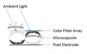
The 1.2 mm thick electronic ink display consists of a pixel electrode layer, a layer of microcapsules, and a color filter array (Figure 1). The electrode layer enables the system to attract and repel the charged particles within each of the microcapsules to a resolution that exceeds 200 DPI (dots per inch). Within each microcapsule are positively charged white particles and negatively charged black particles which are all suspended within a clear viscous fluid. When the electrode layer applies a positive or negative electric field near each microcapsule, the charged particles within it move to the front or back of the microcapsule depending on whether it is attracted or repelled from the electrode layer.

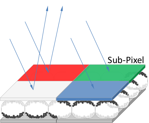
When the white particles are at the top of the microcapsule, the ambient light is reflected from the surface of the display. Likewise, when the black particles are at the top of the microcapsule, the ambient light is absorbed. Note that the electrode does not need to align with each microcapsule because the electric field affects the particles within the microcapsule irrespective of the border of the capsule; this means that a microcapsule can have white and black particles at the top of the capsule at the same time (Figure 2). By placing a color filter array over the field of microcapsules, it becomes possible to select which colors are visible by moving the white particles under the appropriate color segments in the filter array. Unlike the microcapsule layer, the electrode layer does need to tightly correlate with the color filter array.

The color filter array consists of a red, green, blue, and white sub-pixel segment at each pixel location. Controlling the absorption or reflection of light at each segment yields 4096 different color combinations.

This display uses an RGBW (Red, Green, Blue, and White) color system that delivers a minimum contrast ratio of 10:1 (Figure 2). For example, to show red, you would bring the white particles forward in the microcapsules under the red segment of the filter array while bringing the black particles forward in the other segments of the array. To present a brighter red color, you can also bring the white particles forward under the white segment of the filter array – however, the color will appear less saturated. To present a black image, the black particles are brought forward under all of the color segments. To present a white image, the white particles are brought forward under all of the color segments because under the RGBW color system, white is the result of all of the colors mixed together.

As electronic ink technology continues to mature and find a home in more applications, I expect that we will see developers take advantage of the fact that these types of displays can be formed into any shape and can be bent without damaging them. The fact that the color displays rely on the same chemistry as the monochrome ones suggests that adding color to a monochrome-based application should not represent a huge barrier to implement. However, the big challenge limiting where electronic ink displays can be used is how to implement the electrode layer such that it still delivers good enough resolution in whatever the final shape or shapes the display must support.