Capacitive touch sensing differs from resistive touch sensing in that it relies on the conductive properties of the human finger rather than pressure on the touch surface. One major difference is that a capacitive touch sensor will not work with a stylus made of non-conductive material, such as plastic, nor will it work if the user is wearing non-conductive gloves without a high sensitivity. In contrast, both plastic styluses and gloved fingers can work fine with resistive touch sensors.
Capacitive touch solutions are used in touchscreens applications, such as on touch smartphones, as well as for replacing mechanical buttons in end equipment. The techniques to sensing a touch are similar, but the materials that each design uses may be different. Capacitive touch surfaces rely on a layer of charge-storing material, such as ITO (indium tin oxide), copper, or printed ink, coated on or sandwiched between insulators, such as glass. Copper layered on a PCB works for replacing mechanical buttons. ITO is a transparent conductor that allows a capacitive sensor to be up to 90% transparent in a single layer implementation, and that makes it ideal for touchscreen applications where the user needs to be able to see through the sensing material.
In general, oscillator circuits apply a consistent voltage across the capacitive layer. When a conductive material or object, such as a finger, gets close enough or touches the sensor surface, it draws current and causes the electrical frequencies to fluctuate each of the oscillator circuits. The touch sensing controller can correlate the differences at each oscillator to detect and infer the point or points of contact.
Capacitive touch sensors can employ different approaches to detect and determine the location of a user’s finger on the touch surface. The trade-offs for each approach provide the differentiation that drive the competing capacitive touch offerings available today.Mechanical button replacement generally does not need to determine the exact position of the user’s finger, so they can use a surface capacitance implementation.

A cross sectional view of a surface capacitive touch sensor to replace a mechanical button. (courtesy Cypress)
Surface capacitance implementationsrely on coating only one side of the insulator with a conductive layer. Applying a small voltage to the layer produces a uniform electrostatic field that forms a dynamic capacitor when the user’s finger touches the uncoated surface. In the figure (courtesy Cypress), a simple parallel plate capacitor with two conductors is separated by a dielectric layer. Most of the energy is concentrated between the plates, but some of the energy spills over into the area outside the plates. The electric field lines associated with this effect are called fringing fields, and placing a finger near these fields adds conductive surface area that the system can measure.Surface capacitance implementations are subject to parasitic capacitive coupling and need calibration during manufacturing.
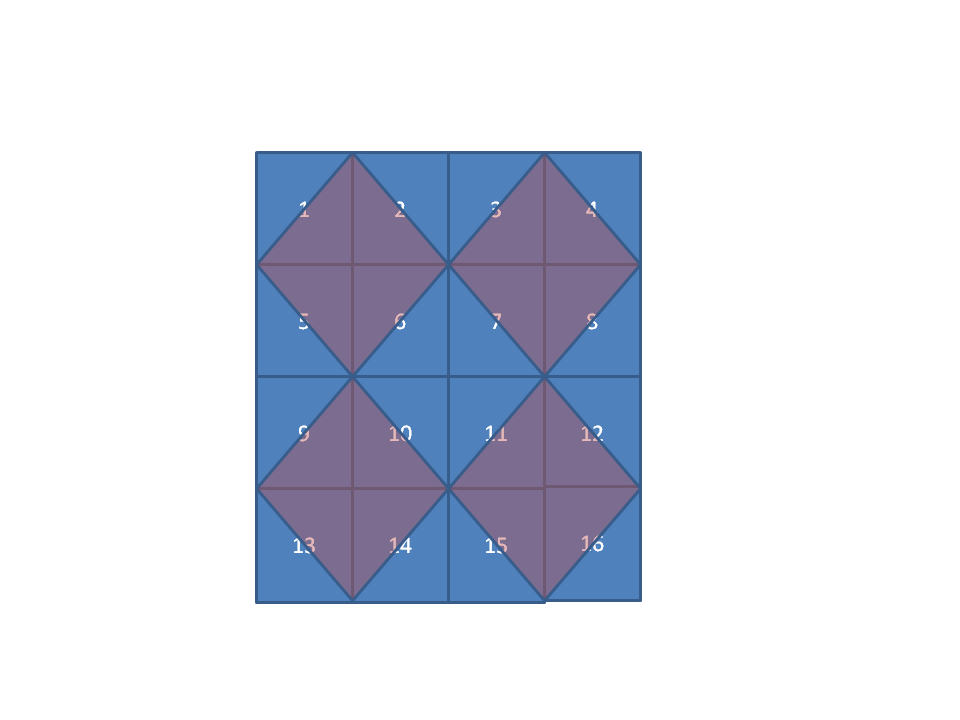
The cross section figure is for a single button, but button replacement designs for multiple buttons placed near each other do not require a one-to-one sensing pad to button. For example, the 4×4 set of buttonscould be implemented with as few as 9 pads by overlapping each touch pad in a diamond shape across up to four buttons. The touch controller can then correlate a touch across multiple pads to a specific button. Touching one of the four corner buttons (1, 4, 13, and 16) requires that only one pad register a touch. To detect a touch on any of the other buttons requires the controller to detect a simultaneous touch on two pads. To support multiple button presses at the same time, the pad configuration would need to add a pad at each corner so that the corner buttons could be uniquely identified.
The next post will discuss touch location detection for touchscreen implementations.
Tags: Capacitive Touch, Touch Sensing

