Entries Tagged ‘Touch Sensing’

Looking at Tesla Touch

Friday, January 14th, 2011 by Robert Cravotta

The team at Disney Research has been working on the Tesla Touch prototype for almost a year. Tesla Touch is a touchscreen feedback technology that relies on the principles of electrovibration to simulate textures on a user’s fingertips. This article expands on the overview of the technology I wrote earlier, and it is based on a recent demonstration meeting at CES that I had with Ivan Poupyrev and Ali Israr, members of the Tesla Touch development team.

The first thing to note is that the Tesla Touch is a prototype; it is not a productized technology just yet. As with any promising technology, there are a number of companies working with the Tesla Touch team to figure out how they might integrate the technology into their upcoming designs. The concept behind the Tesla Touch is based on technology that researchers in the 1950’s were working on to assist blind people. The research fell dormant and the Tesla Touch team has revived it. The technology shows a lot of interesting promise, but I suspect the process of making it robust enough for production designs will uncover a number of use-case challenges (like it probably did for the original research team).

The Tesla Touch controller modulates a periodic electrostatic charge across the touch surface which attracts and repels the electrons in the user’s fingertip towards or away from the touch surface – in effect, varying the friction the user experiences while moving their finger across the surface. Ali has been characterizing the psychophysics of the technology over the last year to understand how people perceive tactile sensations of the varying electrostatic field. Based on my experience with sound bars last week (which I will write about in another article), I suspect the controller for this technology will need to be able to manage a number of usage profiles to accommodate different operating conditions as well as differences between how users perceive the signal it produces.

Ali shared that the threshold to feel the signal was an 8V peak-to-peak modulation; however, the voltage swing on the prototype ranged from 60 to 100 V. The 80 to 100 V signal felt like a comfortable tug on my finger; the 60 to 80 V signal presented a much lighter sensation.Because our meeting was more than a quick demonstration in a booth, I was able to uncover one of the use-case challenges. When I held the unit in my hand, the touch feedback worked great; however, if I left the unit on the table and touched it with only one hand, the touch feedback was nonexistent. This was in part because the prototype is based on the user providing the ground for the system. Ivan mentioned that the technology can work without the user grounding it, but that it requires the system to use larger voltage swings.

In order for the user to feel the feedback, their finger must be in motion. This is consistent with how people experience touch, so there is no disconnect between expectations and what the system can deliver. The expectation that the user will more easily sense the varying friction with lateral movement of their finger is also consistent with observations that the team at Immersion, a mechanical-based haptics company, shared with me when simulating touch feedback on large panels with small motors or piezoelectric strips.

The technology prototype used a capacitive touch screen – demonstrating that the touch sensing and the touch feedback systems can work together. The prototype was modulating the charge on the touch surface at up to a 500 Hz rate which is noticeably higher than the 70Hz rate of the its touch sensor. A use-case challenge for this technology is that it requires a conductive material or substance at the touch surface in order to convey texture feedback to the user. While a 100 V swing is sufficient for a user to sense feedback with their finger, it might not be large enough of a swing to sense it through an optimal stylus. Using gloves will also impair or prevent the user from sensing the feedback.

A fun surprise occurred during one of the demonstration textures. In this case, the display showed a drinking glass. When I rubbed the display away from the drinking glass, the surface was a normal smooth surface. When I rubbed over the surface that showed the drinking glass, I felt a resistance that met my expectation for the glass. I then decided to rub repeated over that area to see if the texture would change and was rewarded with a sound similar to rubbing/cleaning a drinking glass with your finger. Mind you, the sound did not occur when I rubbed the other parts of the display.

The technology is capable of conveying coarse texture transitions, such as from a smooth surface to a rough or heavy surface. It is able to convey a sense of bumps and boundaries through varying the amount of tugging your finger feels on the touch surface. I am not sure when or if it can convey subtle or soft textures – however, there are so many ways to modulate the magnitude, shape, frequency, and repetition or the charge on the plate, that those types of subtle feedbacks may be possible in a production implementation.

I suspect a tight coupling between the visual and touch feedback is an important characteristic for the user to accept the touch feedback from the system. If the touch signal precedes or lags the visual cue, it is disconcerting and confusing. I was able to experience this on the prototype by using two fingers on the display at the same time. The sensing control algorithm only reports back a single touch point, so it would average the position between the two (or more) fingers. This is acceptable in the prototype as it was not a demonstration of a multi-touch system, but it did allow me to receive a feedback on my fingertips that did not match what my fingers were actually “touching” on the display.

There is a good reason why the prototype did not support multi-touch. The feedback implementation applies a single charge across the entire touch surface. That means any and all fingers that are touching the display will (roughly) feel the same thing. This is more of an addressing problem; the system was using a single electrode. It might be possible in later generations to lay out different configurations so that the controller can drive different parts of the display with different signals. At this point, it is a similar constraint to what mechanical feedback systems contend with also. However, one advantage that the Tesla Touch approach has over the mechanical approach is that only the finger touching the display senses the feedback signal. In contrast, the mechanical approach relays the feedback not just to the user’s fingers, but also their other hand which is holding the device.

A final observation involves the impact of applying friction to our fingers in a context we are not used to doing. After playing with the prototype for quite some time, I felt a sensation in my fingertip that took up to an hour to fade away. I suspect my fingertip would feel similarly if I rubbed it on a rough surface for an extended time. I suspect with repeated use over time, my fingertip would develop a mini callous and the sensation would no longer occur.

This technology shows a lot of promise. It offers a feedback approach that includes no moving parts, but it may have a more constrained set of use-cases,versus other types of feedback, where it is able to provide useful feedback to the user.

Adding texture to touch interfaces

Friday, December 17th, 2010 by Robert Cravotta

I recently heard about another approach to providing feedback to touch interfaces (Thank you Eduardo). TeslaTouch is a technology developed at Disney Research that uses principles of electrovibration to simulate textures on a user’s finger tips. I will be meeting with TeslaTouch at CES and going through a technical demonstration, so I hope to be able to share good technical details after that meeting. In the meantime, there are videos at the site that provide a high level description of the technology.

The feedback controller uniformly applies a periodic electrostatic charge across the touch surface. By varying the sign (and possibly magnitude) of the charge, the electrons in the user’s fingertip will be drawn towards or away from the surface – effective creating a change in friction on the touch surface. Current prototypes are able to use signals as low as 8V to generate tactile sensations. No electric charge passes through the user.

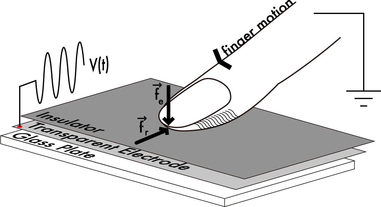
By varying over time the electric charge across the electrode layer, this touch sensor and feedback surface can simulate textures on a user’s finger by attracting and repelling the electrons in the user’s finger to and from the touch surface (courtesy TeslaTouch).

The figure shows a cross section of the touch surface which consists of a layer of glass overlaid with a layer of transparent electrode, which is covered by an insulator. Varying the voltage across the electrode layer changes the relative friction coefficients from pushing a finger (Fe) into the touch surface and dragging a finger across it (Fr). It is not clear how mature this technology currently is other than the company is talking about prototype units.

One big feature of this approach to touch feedback is that it does not rely on mechanical actuators typically used in haptic feedback approaches. The lack of moving parts should contribute to a higher reliability when compared to the electromechanical alternatives. However, it is not clear the this technology would work through gloves or translate through a stylus – of which the electromechanical approach can accommodate.

What are the questions you would like most answered about this technology? I am hopeful that I can dig deep into the technology at my CES meeting and pass on what I find in a follow-up here. Either email me or post the questions you would most like to see answered. The world of touch user interfaces is getting more interesting each day.

Capacitive button sense algorithm

Tuesday, November 23rd, 2010 by Robert Cravotta

There are many ways to use capacitive touch for user interfaces; one of the most visible ways is via a touch screen. An emerging use for capacitive touch in prototype devices is to sense the user’s finger on the backside or side of the device. Replacing mechanical buttons is another “low hanging fruit” for capacitive touch sensors. Depending on how the touch sensor is implemented, the application code may be responsible for working with low level sensing algorithms, or it may be able to take advantage of higher levels of abstraction when the touch use cases are well understood.

The Freescale TSSEVB provides a platform for developers to work with capacitive buttons placed in slider, rotary, and multiplexed configurations. (courtesyFreescale)

Freescale’s Xtrinsic TSS (touch sensing software) library and evaluation board provides an example platform for building touch sensing into a design using low- and mid-level routines. The evaluation board (shown in the figure) provides electrodes in a variety of configuration including multiplexed buttons, LED backlit buttons, different sized buttons, and buttons grouped together to form slider, rotary, and keypad configurations. The Xtrinsic TSS supports 8- and 32-bit processors (the S08 and Coldfire V1 processor families), and the evaluation board uses an 8-bit MC9S08LG32 processor for the application programming. The board includes a separate MC9S08JM60 communication processor that acts as a bridge between the application and the developer’s workstation. The evaluation board also includes an on-board display.

The TSS library supports up to 64 electrodes. The image of the evaluation board highlights some of the ways to configure electrodes to maximize functionality while using fewer electrodes. For example, the 12 button keypad uses 10 electrodes (numbered around the edge of the keypad) to detect the 12 different possible button positions. Using 10 electrodes allows the system to detect multiple simultaneous button presses. If you could guarantee that only one button would be pressed at a time, you could reduce the number of electrodes to 8 by eliminating the two small corner electrodes numbered 2 and 10 in the image. Further in the background of the image are four buttons with LEDs in the middle as well as a rotary and slider bar.

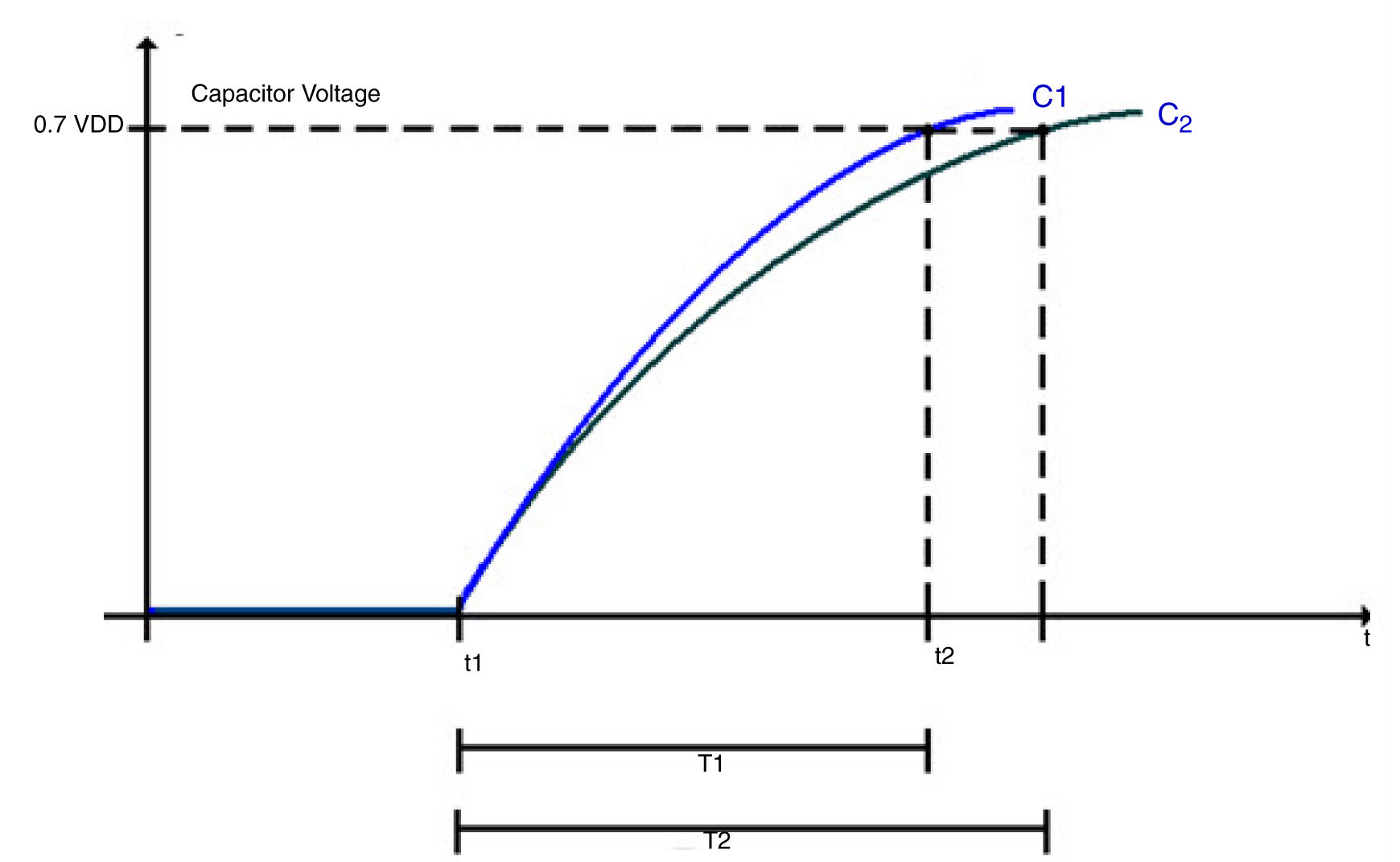
The charge time of the sensing electrode is extended by the additional capacitance of a finger touching the sensor area.

Each electrode in the touch sensing system acts like a capacitor with a charging time defined as T = RC. An external pull-up resistor limits the current to charge the electrode which in turn affects the charging time. Additionally, the presence or lack of a user’s finger near the electrode affects the capacitance of the electrode which also affects the charging time.

In the figure, C1 is the charging curve and T1 is the time to charge the electrode to VDD when there is no extra capacitance at the electrode (no finger present). C2 is the charging curve and T2 is the time to charge the electrode when there is extra capacitance at the electrode (finger present).The basic sensing algorithm relies on noting the time difference between T1 and T2 to determine if there is a touch or not.

The TSSEVB supports three different ways to control and measure the electrode: GPIO, the KBI or pin interrupts, and timer input capture. In each case, the electrode defaults to an output high state. To start measuring, the system sets the electrode pins output low to discharge the capacitor. By setting the electrode pin to a high impedance state, the capacitor will start charging. The different measurement implementations set and measure the electrode state slightly differently, but the algorithm is functionally the same.

The algorithm to detect a touch consists of 1) starting a hardware timer; 2) starting the electrode charging; 3) waiting for the electrode to charge (or a timeout to occur); and 4) returning the value of the timer. One difference between the different modes is whether the processor is looping (GPIO and timer input capture) or in a wait state (KBI or pin interrupt) which can affect whether you can perform any other tasks during the sensing.

There are three parameters which will affect the performance of the TSS library: the timer frequency, the pull-up resistor value, and the system power voltage. The timer frequency affects the minimum capacitance measurable. The system power voltage and pull-resistor affect the voltage trip point and how quickly the electrode charges. The library uses at least one hardware timer, so the system clock frequency affects the ability of the system to detect a touch because the frequency affects the minimum capacitance value detected per timer count.

The higher clock the frequency, the smaller the amount of capacitance the system can detect. If the clock rate is too fast for the charging time, the timer can overflow. If the clock rate is too slow, the system will be more susceptible to noise and have a harder time reliably detecting a touch. When I was first working with the TSSEVB, we chose less than optimally values and the touch sensing did not work very well. After figuring out there was a mismatch in the scaling value that we chose, the performance of the touch sensing drastically improved.

The library supports what Freescale calls Turbo Sensing, which is an alternative technique to measure charge time by counting bus ticks instead of using a timer. This increases the system integration flexibility and makes measurement faster with less noise and supports interrupt conversions. We did not have time to try out the turbo sensing method.

The decoder functions, such as for the keypad, slider, or rotary configurations, support a higher level of abstraction to the application code. For example, the keypad configuration relies on each button mapping to two electrodes charging at the same time. As an example, in the figure, the button numbered 5 requires electrodes 5 and 8 to charge together as each of those electrodes covers half of the 5 button. The rotary decoder handles more information than the key press decoder because it not only detects when electrode pads have been pressed, but it reports from what direction (of two possibilities) the pad was touched and how many pads experienced some displacement. This allows the application code to control the direction and speed of moving through a list. The slider decoder is similar to the rotary decoder except that the ends of the slider do not touch each other.

The size and shape of each electrode pad, as well as the parameters mentioned before, affects the charging time, so the delta in the T1 and T2 times will not necessarily be the same for each button. The charging time for each electrode pad might change as environmental conditions change. However, because detecting a touch is based on a relative difference in the charging time for each electrode, the system provides some resilience to environmental changes.

Replacing Mechanical Buttons with Capacitive Touch

Friday, October 29th, 2010 by Robert Cravotta

Capacitive touch sensing differs from resistive touch sensing in that it relies on the conductive properties of the human finger rather than pressure on the touch surface. One major difference is that a capacitive touch sensor will not work with a stylus made of non-conductive material, such as plastic, nor will it work if the user is wearing non-conductive gloves without a high sensitivity. In contrast, both plastic styluses and gloved fingers can work fine with resistive touch sensors.

Capacitive touch solutions are used in touchscreens applications, such as on touch smartphones, as well as for replacing mechanical buttons in end equipment. The techniques to sensing a touch are similar, but the materials that each design uses may be different. Capacitive touch surfaces rely on a layer of charge-storing material, such as ITO (indium tin oxide), copper, or printed ink, coated on or sandwiched between insulators, such as glass. Copper layered on a PCB works for replacing mechanical buttons. ITO is a transparent conductor that allows a capacitive sensor to be up to 90% transparent in a single layer implementation, and that makes it ideal for touchscreen applications where the user needs to be able to see through the sensing material.

In general, oscillator circuits apply a consistent voltage across the capacitive layer. When a conductive material or object, such as a finger, gets close enough or touches the sensor surface, it draws current and causes the electrical frequencies to fluctuate each of the oscillator circuits. The touch sensing controller can correlate the differences at each oscillator to detect and infer the point or points of contact.

Capacitive touch sensors can employ different approaches to detect and determine the location of a user’s finger on the touch surface. The trade-offs for each approach provide the differentiation that drive the competing capacitive touch offerings available today.Mechanical button replacement generally does not need to determine the exact position of the user’s finger, so they can use a surface capacitance implementation.

A cross sectional view of a surface capacitive touch sensor to replace a mechanical button. (courtesy Cypress)

Surface capacitance implementationsrely on coating only one side of the insulator with a conductive layer. Applying a small voltage to the layer produces a uniform electrostatic field that forms a dynamic capacitor when the user’s finger touches the uncoated surface. In the figure (courtesy Cypress), a simple parallel plate capacitor with two conductors is separated by a dielectric layer. Most of the energy is concentrated between the plates, but some of the energy spills over into the area outside the plates. The electric field lines associated with this effect are called fringing fields, and placing a finger near these fields adds conductive surface area that the system can measure.Surface capacitance implementations are subject to parasitic capacitive coupling and need calibration during manufacturing.

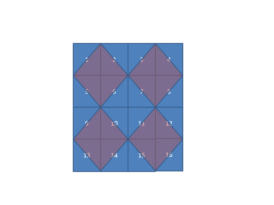
The cross section figure is for a single button, but button replacement designs for multiple buttons placed near each other do not require a one-to-one sensing pad to button. For example, the 4×4 set of buttonscould be implemented with as few as 9 pads by overlapping each touch pad in a diamond shape across up to four buttons. The touch controller can then correlate a touch across multiple pads to a specific button. Touching one of the four corner buttons (1, 4, 13, and 16) requires that only one pad register a touch. To detect a touch on any of the other buttons requires the controller to detect a simultaneous touch on two pads. To support multiple button presses at the same time, the pad configuration would need to add a pad at each corner so that the corner buttons could be uniquely identified.

The next post will discuss touch location detection for touchscreen implementations.

Haptic User Interfaces

Tuesday, October 12th, 2010 by Robert Cravotta

Applications that support touch displays overwhelmingly rely on visual feedback to let the user know what touch event occurred. Some applications support delivering an audio signal to the user, such as a click or beep, to acknowledge that a button or virtual key was pressed. However, in many touch interfaces, there is no physical feedback, such as a small vibration, to let the user know that the system detected a touch of the display.

Contrast this with the design of mechanical keyboards. It is an explicit design decision whether the keys are soft or firm to the touch. Likewise, the “noisiness” of the keys and whether there is an audible and physical click at the end of a key press are the result of explicit choices made by the keyboard designer.

As end devices undergo a few design generations of supporting touch interfaces, I expect that many of them will incorporate haptic technology, such as from Immersion, so as to deliver the sensation of the click at the end of a key press. However, I am currently not aware of how a digital touch interface can dynamically simulate different firmness or softness of the touch display, but something like the Impress squishy display may not be too far away.

Some other interesting possibilities for touch based information and feedback are presented in Fabian Hemmert’s video about shape shifting mobile devices. In the video he demonstrates how designers might implement three different types of shape shifting in a mobile phone form factor.

The first concept is a weight-shifting device that can shift its center of mass. Not only could the device provide a tactile feedback of where the user is touching the display, but it can be used to “point” the user in a direction by making it heavier in the direction it wishes to point. This has the potential to allow a device to guide the user through the city without requiring the user to look at the device.

The second concept is a shape-shifting device that can transform from a flat form to one that is raised on any combination of its four corners. This allows the device to extend an edge or taper a corner toward or away from the user to indicate that there is more information in the indicated direction (such as when looking at a map). A shape-shifting capability can also allow the device to be placed on a flat surface, say a nightstand and allow the device to take on a context specific function – say an alarm clock.

The third concept is a “breathing” device where the designer uses the shifting capabilities of the device to indicate a health state of the device. However, to make the breathing concept more than just an energy drain, it will need to be able to decide whether there is someone around to observe it, so that it can save its energy when it is alone.

The mass- and shape-shifting concepts hold a lot of promise, especially when they are combined together in the same device. It might be sooner than we think when these types of features are available to include in touch interfaces.

Alternative touch interfaces – sensor fusion

Tuesday, September 21st, 2010 by Robert Cravotta

While trying to uncover and highlight different technologies that embedded developers can tap into to create innovative touch interfaces, Andrew commented on e-field technology and pointed to Freescale’s sensors. While exploring proximity sensing for touch applications, I realized that accelerometers represent yet another alternative sensing technology (versus capacitive touch) that can impact how a user can interact with a device. The most obvious examples of this are devices, such as a growing number of smart phones and tablets, which are able to detect their orientation to the ground and rotate the information they are displaying. This type of sensitivity enables interface developers to consider broader gestures that involve manipulating the end device, such as shaking it, to indicate some type of change in context.

Wacom’s Bamboo Touch graphic tablet for consumers presents another example of e-field proximity sensing combined with capacitive touch sensing. In this case, the user can use the sensing surface with an e-field optimized stylus or they can use their finger directly on the surface. The tablet controller detects which type of sensing it should use without requiring the user to explicitly switch between the two sensing technologies. This type of combined technology is finding its way into tablet computers.

I predict the market will see more examples of end devices that seamlessly combine different types of sensing technologies in the same interface space. The different sensing modules working together will enable the device to infer more about the user’s intention, which will in turn, enable the device to better learn and adapt to each user’s interface preferences. To accomplish this, devices will need even more “invisible” processing and database capabilities that allow these devices to be smarter than previous devices.

While not quite ready for production designs, the recent machine touch demonstrations from the Berkeley and Stanford research teams suggest that future devices might even be able to infer user intent by how the user is holding the device – including how firmly or lightly they are gripping or pressing on it. These demonstrations suggest that we will be able to make machines that are able to discern differences in pressure comparable to humans. What is not clear is whether each of these technologies will be able to detect surface textures.

By combining, or fusing, different sensing technologies together, along with in-device databases, devices may be able to start recognizing real world objects – similar to the Microsoft Surface. It is becoming within our grasp for devices to start recognizing each other without requiring explicit electronic data streams flowing between those devices.

Do you know of other sensing technologies that developers can combine together to enable smarter devices that learn how their user communicates rather than requiring the user to learn how to communicate with the device?

Giving machines a fine sense of touch

Tuesday, September 14th, 2010 by Robert Cravotta

Two articles were published online on the same day (September 12, 2010) in Nature Materials that describe the efforts of two research teams at UC Berkeley and Stanford University that have each developed and demonstrated a different approach for building artificial skin that can sense very light touches. Both systems have reached a pressure sensitivity that is comparable to what a human relies on to perform everyday tasks. The sensitivity of these systems can detect pressure changes that are less than a kilopascal; this is an improvement over earlier approaches that could only detect pressures of tens of kilopascals.

The Berkeley approach, dubbed “e-skin”, uses germanium/silicon nanowire “hairs” that are grown on a cylindrical drum and then rolled onto a sticky polyimide film substrate, but the substrate can be made from plastics, paper, or glass. The nanowires are deposited onto the substrate to form an orderly structure. The demonstrated e-skin consists of a 7x7cm surface consisting of an 18×19 pixel square matrix; each pixel contains a transistor made of hundreds of the nanowires.A pressure sensitive rubber was integrated on top of the matrix to support sensing. The flexible matrix is able to operate with less than a 5V power supply, and it has been able to continue operating after being subjected to more than 2,000 bending cycles.

In contrast, the Stanford approach, sandwiches a thin film of rubber molded into a grid of tiny pyramids, packing up to 25 million pyramids per cm2, between two parallel electrodes. The pyramid grid makes the rubber behave like an ideal spring that supports compression and rebound of the rubber that is fast enough to distinguish between multiple touches that follow each other in quick succession. Pressure on the sensor compresses the rubber film and changes the amount of electrical charge it can store which enables the controller to detect the change in the sensor. According to the team, the sensor can detect the pressure exerted by a 20mg bluebottle fly carcass placed on the sensor. The Stanford team has been able to manufacture a sheet as large as 7x7cm, similar to the Berkeley e-skin.

I am excited by these two recent developments in machine sensing. The uses for this type of touch sensing are endless such as in industrial, medical, and commercial applications. A question comes to mind – these are both sheets (arrays) of multiple sensing points – how similar will the detection and recognition algorithms be to the touch interfaces and vision algorithms that are being developed today? Or will it require a completely different approach and thought process to interpret this type of touch sensing?