Entries Tagged ‘Capacitive Touch’

The battle for multi-touch

Tuesday, April 12th, 2011 by Robert Cravotta

As with most technologies used in the consumer space, they take a number of years to gestate before they mature enough and gain visibility to end users. Capacitive-based multi-touch technology burst into the consumer conscience with the introduction of the iPhone. Dozens of companies have since entered the market to provide capacitive touch technologies to support new designs and applications. The capabilities that capacitive touch technology can support, such as improved touch sensing for multiple touches, detecting and filtering unintended touches (such as palm and cheek detection), as well as supporting a stylus, continues to evolve and improve.

Capacitive touch enjoys a very strong position providing the technology for multi-touch applications; however, there are other technologies that are or will likely be vying for a larger piece of the multi-touch pie. A potential contender is the vision-based multi-touch technology found in the Microsoft Surface. However, at the moment of this writing, Microsoft has indicated that it is not focusing its effort for the pixel sense technology toward the embedded market, so it may be a few years before the technology is available to embedded developers.

The $7600 price tag for the newest Surface system may imply that the sensing technology is too expensive for embedded systems, but it is important to realize that this price point supports a usage scenario that vastly differs from a single user device. First, the Surface provides a 40 inch diagonal touch/display surface that four people can easily access and use simultaneously. Additionally, the software and processing resources contained within the system are sized to handle 50 simultaneous touch points. Shrink both of these capabilities down to a single user device and the pixel sense technology may become quite price competitive.

Vision-based multi-touch works with more than a user’s fingers; it can also detect, recognize and interact with mundane, everyday objects, such as pens, cups, paint brushes, as well as touch interface specific objects such as styli. The technology is capable, if you provide enough compute capability, to distinguish and handle touches and hovering of fingers and objects over the touch surface differently.I’m betting as the manufacturing process for the pixel sense sensors matures, the lower price points will make a compelling case for focusing development support to the embedded community.

Resistive touch technology is another multi-touch contender. It has been the work horse for touch applications for decades, but its ability (or until recently, lack of) to support multi-touch designs has been one of its significant shortcomings. One advantage that resistive touch has enjoyed over capacitive touch for single-touch applications is a lower cost point to incorporate it into a design. Over the last year or so, resistive touch has evolved to be able to support multi-touch designs by using more compute processing in the sensor to resolve the ghosting issues in earlier resistive touch implementations.

Similar to vision-based multi-touch, resistive touch is able to detect contact with any normal object because resistive touch relies on a mechanical interface. Being able to detect contact with any object provides an advantage over capacitive touch because capacitive touch sensing can only detect objects, such as a human finger or a special conductive-tipped stylus, with conductive properties that can draw current from the capacitive field when placed on or over the touch surface. Capacitive touch technology also continues to evolve, and support for thin, passive styli (with an embedded conductive tip) is improving.

Each technology offers different strengths and capabilities; however, the underlying software and embedded processors in each approach must be able to perform analogous functions in order to effectively support multi-touch applications. A necessary capability is the ability to distinguish between explicit and unintended touches. This capability requires the sensor processor and software to be able to continuously track many simultaneous touches and assign a context to each one of them. The ability to track multiple explicit touches relative to each other is necessary to be able to recognize both single- and multi-touch gestures, such as swipes and pinches. Recognizing unintended touches involves properly ignoring when the user places their palm or cheek over the touch area as well as touching the edges of the touch surface with their fingers that are gripping the device.

A differentiating capability for touch sensing is minimizing the latency between when the user makes an explicit touch and when the system responds or provides the appropriate feedback to that touch. Longer latencies can affect the user’s experience in two detrimental ways in that the collected data for the touch or gesture has poor quality or the delay in feedback confuses the user. One strategy to minimize latency is to sample or process less points when a touch (or touches) is moving; however, this risks losing track of small movements that can materially affect analyzing the user’s movement such as when writing their signature. Another strategy to accommodate tracking the movement of a touch without losing data is to allow a delay in displaying the results of the tracking. If the delay is too long though, the user may try to compensate and try to restart their movement – potentially confusing or further delaying the touch sensing algorithms. Providing more compute processing helps in both of these cases, but it also increases the cost and energy draw of the system.

While at CES, I experienced multi-touch with all three of these technologies. I was already familiar with the capabilities of capacitive touch. The overall capabilities and responsiveness of the more expensive vision-based system met my expectations; I expect the price point for vision-based sensing to continue its precipitous fall into the embedded space within the next few years. I had no experience with resistive-based multi-touch until the show. I was impressed by the demonstrations that I saw from SMK and Stantum. The Stantum demonstration was on a prototype module, and I did not even know the SMK module was a resistive based system until the rep told me. The pressure needed to activate a touch felt the same as using a capacitive touch system (however, I am not an everyday user of capacitive touch devices). As these technologies continue to increasingly overlap in their ability to detect and appropriately ignore multiple touches within a meaningful time period, their converging price points promise an interesting battle as each technology finds its place in the multi-touch market.

Capacitive button sense algorithm

Tuesday, November 23rd, 2010 by Robert Cravotta

There are many ways to use capacitive touch for user interfaces; one of the most visible ways is via a touch screen. An emerging use for capacitive touch in prototype devices is to sense the user’s finger on the backside or side of the device. Replacing mechanical buttons is another “low hanging fruit” for capacitive touch sensors. Depending on how the touch sensor is implemented, the application code may be responsible for working with low level sensing algorithms, or it may be able to take advantage of higher levels of abstraction when the touch use cases are well understood.

The Freescale TSSEVB provides a platform for developers to work with capacitive buttons placed in slider, rotary, and multiplexed configurations. (courtesyFreescale)

Freescale’s Xtrinsic TSS (touch sensing software) library and evaluation board provides an example platform for building touch sensing into a design using low- and mid-level routines. The evaluation board (shown in the figure) provides electrodes in a variety of configuration including multiplexed buttons, LED backlit buttons, different sized buttons, and buttons grouped together to form slider, rotary, and keypad configurations. The Xtrinsic TSS supports 8- and 32-bit processors (the S08 and Coldfire V1 processor families), and the evaluation board uses an 8-bit MC9S08LG32 processor for the application programming. The board includes a separate MC9S08JM60 communication processor that acts as a bridge between the application and the developer’s workstation. The evaluation board also includes an on-board display.

The TSS library supports up to 64 electrodes. The image of the evaluation board highlights some of the ways to configure electrodes to maximize functionality while using fewer electrodes. For example, the 12 button keypad uses 10 electrodes (numbered around the edge of the keypad) to detect the 12 different possible button positions. Using 10 electrodes allows the system to detect multiple simultaneous button presses. If you could guarantee that only one button would be pressed at a time, you could reduce the number of electrodes to 8 by eliminating the two small corner electrodes numbered 2 and 10 in the image. Further in the background of the image are four buttons with LEDs in the middle as well as a rotary and slider bar.

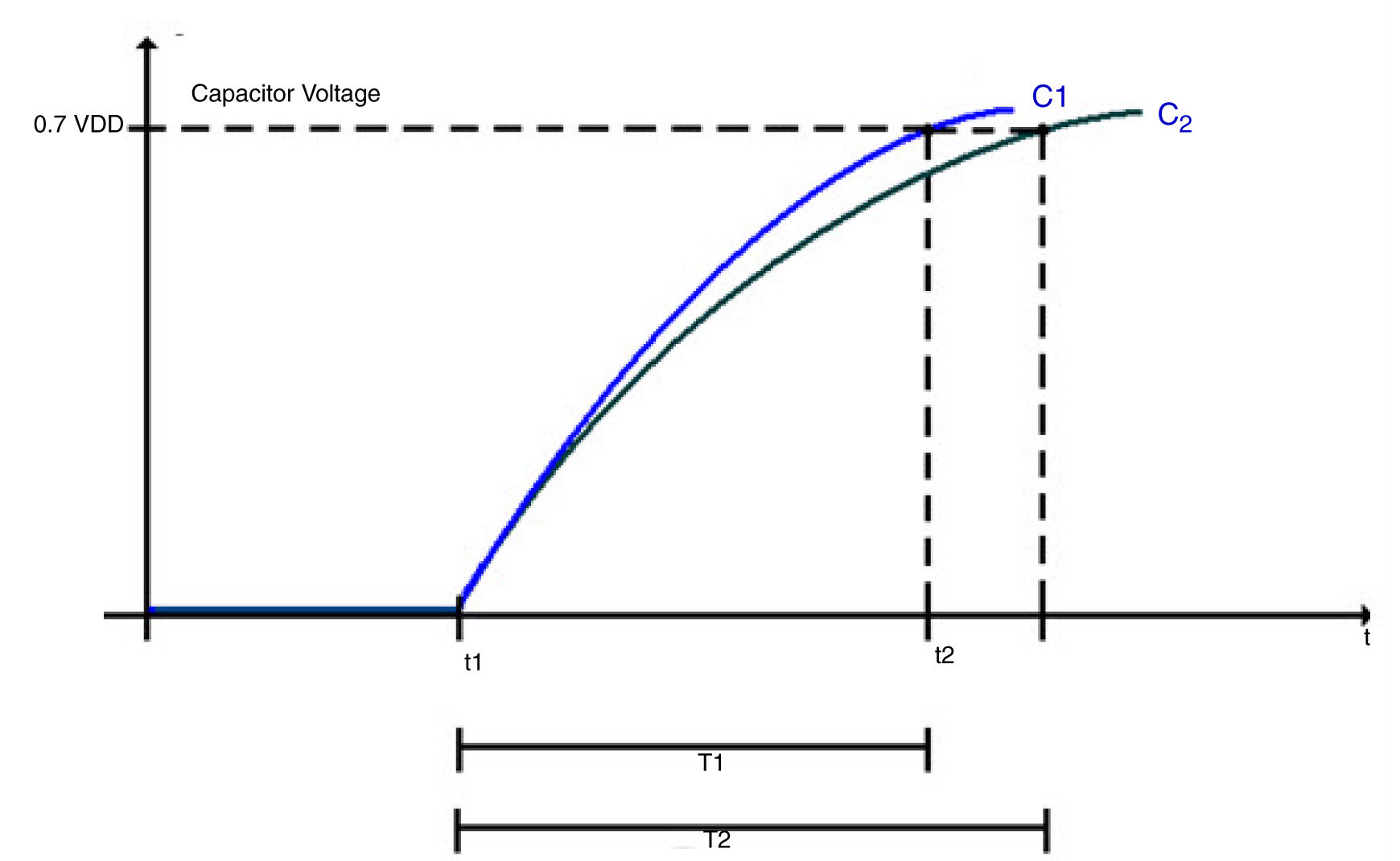
The charge time of the sensing electrode is extended by the additional capacitance of a finger touching the sensor area.

Each electrode in the touch sensing system acts like a capacitor with a charging time defined as T = RC. An external pull-up resistor limits the current to charge the electrode which in turn affects the charging time. Additionally, the presence or lack of a user’s finger near the electrode affects the capacitance of the electrode which also affects the charging time.

In the figure, C1 is the charging curve and T1 is the time to charge the electrode to VDD when there is no extra capacitance at the electrode (no finger present). C2 is the charging curve and T2 is the time to charge the electrode when there is extra capacitance at the electrode (finger present).The basic sensing algorithm relies on noting the time difference between T1 and T2 to determine if there is a touch or not.

The TSSEVB supports three different ways to control and measure the electrode: GPIO, the KBI or pin interrupts, and timer input capture. In each case, the electrode defaults to an output high state. To start measuring, the system sets the electrode pins output low to discharge the capacitor. By setting the electrode pin to a high impedance state, the capacitor will start charging. The different measurement implementations set and measure the electrode state slightly differently, but the algorithm is functionally the same.

The algorithm to detect a touch consists of 1) starting a hardware timer; 2) starting the electrode charging; 3) waiting for the electrode to charge (or a timeout to occur); and 4) returning the value of the timer. One difference between the different modes is whether the processor is looping (GPIO and timer input capture) or in a wait state (KBI or pin interrupt) which can affect whether you can perform any other tasks during the sensing.

There are three parameters which will affect the performance of the TSS library: the timer frequency, the pull-up resistor value, and the system power voltage. The timer frequency affects the minimum capacitance measurable. The system power voltage and pull-resistor affect the voltage trip point and how quickly the electrode charges. The library uses at least one hardware timer, so the system clock frequency affects the ability of the system to detect a touch because the frequency affects the minimum capacitance value detected per timer count.

The higher clock the frequency, the smaller the amount of capacitance the system can detect. If the clock rate is too fast for the charging time, the timer can overflow. If the clock rate is too slow, the system will be more susceptible to noise and have a harder time reliably detecting a touch. When I was first working with the TSSEVB, we chose less than optimally values and the touch sensing did not work very well. After figuring out there was a mismatch in the scaling value that we chose, the performance of the touch sensing drastically improved.

The library supports what Freescale calls Turbo Sensing, which is an alternative technique to measure charge time by counting bus ticks instead of using a timer. This increases the system integration flexibility and makes measurement faster with less noise and supports interrupt conversions. We did not have time to try out the turbo sensing method.

The decoder functions, such as for the keypad, slider, or rotary configurations, support a higher level of abstraction to the application code. For example, the keypad configuration relies on each button mapping to two electrodes charging at the same time. As an example, in the figure, the button numbered 5 requires electrodes 5 and 8 to charge together as each of those electrodes covers half of the 5 button. The rotary decoder handles more information than the key press decoder because it not only detects when electrode pads have been pressed, but it reports from what direction (of two possibilities) the pad was touched and how many pads experienced some displacement. This allows the application code to control the direction and speed of moving through a list. The slider decoder is similar to the rotary decoder except that the ends of the slider do not touch each other.

The size and shape of each electrode pad, as well as the parameters mentioned before, affects the charging time, so the delta in the T1 and T2 times will not necessarily be the same for each button. The charging time for each electrode pad might change as environmental conditions change. However, because detecting a touch is based on a relative difference in the charging time for each electrode, the system provides some resilience to environmental changes.

Replacing Mechanical Buttons with Capacitive Touch

Friday, October 29th, 2010 by Robert Cravotta

Capacitive touch sensing differs from resistive touch sensing in that it relies on the conductive properties of the human finger rather than pressure on the touch surface. One major difference is that a capacitive touch sensor will not work with a stylus made of non-conductive material, such as plastic, nor will it work if the user is wearing non-conductive gloves without a high sensitivity. In contrast, both plastic styluses and gloved fingers can work fine with resistive touch sensors.

Capacitive touch solutions are used in touchscreens applications, such as on touch smartphones, as well as for replacing mechanical buttons in end equipment. The techniques to sensing a touch are similar, but the materials that each design uses may be different. Capacitive touch surfaces rely on a layer of charge-storing material, such as ITO (indium tin oxide), copper, or printed ink, coated on or sandwiched between insulators, such as glass. Copper layered on a PCB works for replacing mechanical buttons. ITO is a transparent conductor that allows a capacitive sensor to be up to 90% transparent in a single layer implementation, and that makes it ideal for touchscreen applications where the user needs to be able to see through the sensing material.

In general, oscillator circuits apply a consistent voltage across the capacitive layer. When a conductive material or object, such as a finger, gets close enough or touches the sensor surface, it draws current and causes the electrical frequencies to fluctuate each of the oscillator circuits. The touch sensing controller can correlate the differences at each oscillator to detect and infer the point or points of contact.

Capacitive touch sensors can employ different approaches to detect and determine the location of a user’s finger on the touch surface. The trade-offs for each approach provide the differentiation that drive the competing capacitive touch offerings available today.Mechanical button replacement generally does not need to determine the exact position of the user’s finger, so they can use a surface capacitance implementation.

A cross sectional view of a surface capacitive touch sensor to replace a mechanical button. (courtesy Cypress)

Surface capacitance implementationsrely on coating only one side of the insulator with a conductive layer. Applying a small voltage to the layer produces a uniform electrostatic field that forms a dynamic capacitor when the user’s finger touches the uncoated surface. In the figure (courtesy Cypress), a simple parallel plate capacitor with two conductors is separated by a dielectric layer. Most of the energy is concentrated between the plates, but some of the energy spills over into the area outside the plates. The electric field lines associated with this effect are called fringing fields, and placing a finger near these fields adds conductive surface area that the system can measure.Surface capacitance implementations are subject to parasitic capacitive coupling and need calibration during manufacturing.

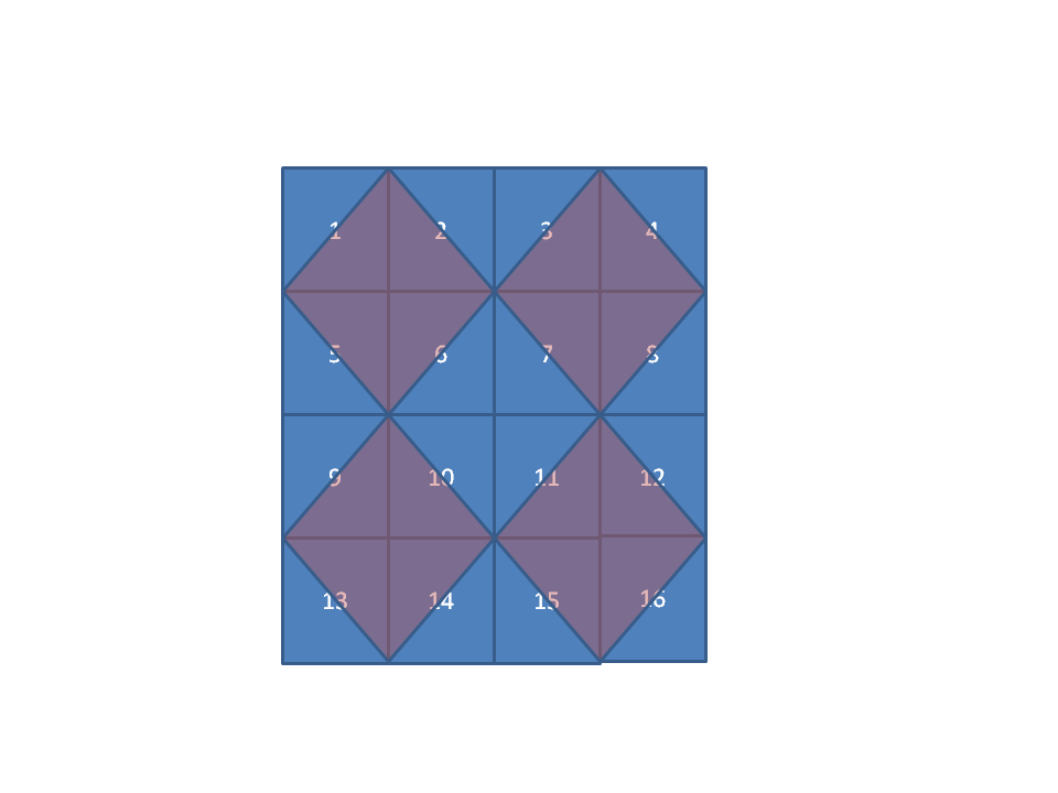
The cross section figure is for a single button, but button replacement designs for multiple buttons placed near each other do not require a one-to-one sensing pad to button. For example, the 4×4 set of buttonscould be implemented with as few as 9 pads by overlapping each touch pad in a diamond shape across up to four buttons. The touch controller can then correlate a touch across multiple pads to a specific button. Touching one of the four corner buttons (1, 4, 13, and 16) requires that only one pad register a touch. To detect a touch on any of the other buttons requires the controller to detect a simultaneous touch on two pads. To support multiple button presses at the same time, the pad configuration would need to add a pad at each corner so that the corner buttons could be uniquely identified.

The next post will discuss touch location detection for touchscreen implementations.