Are you, or someone you know, using voting within your embedded system designs?

Wednesday, November 3rd, 2010 by Robert Cravotta

With the midterm elections in the United States winding down, I thought I’d try to tie embedded design concepts to the process of elections. On some of the aerospace projects I worked on, we used voting schemes as fault tolerant techniques. In some cases, because we could not trust the sensors, we used multiple sensors, and performed voting among the sensor controllers (along with separate and independent filtering) to improve the quality of the data that we used for our control algorithms. We might use multiple of the same type of sensor, and in some cases we would use sensors that differed from each other significantly so that they would not be susceptible to the same types of bad readings.

I did a variety of searches on fault tolerance and voting to see if there was any recent material on the topic. There was not a lot of material available, and what was available was scholarly, and I was generally not able to download the files. It is possible I did a poor job choosing my search terms. However, this lack of material made me wonder if people are using the technique at all and/or has it evolved into a different form. In this case, sensor fusion.

Sensor fusion is the practice of combining data derived from sensors from disparate sources to deliver “better” data than would be possible if these sources were used individually. “Better” in this case can mean more accurate, complete, reliable data. From this perspective, the fusion of the data is not strictly a voting scheme, but there are some similarities with the original concept.

This leads me to this week’s question. Are you, or someone you know, using voting or sensor fusion within embedded system designs? As systems continue to increase in complexity, the need for robust design principles that can enable systems to correctly operate with less-than-perfect components becomes more relevant. Is the voting schemes of yesterday still relevant, or have they evolved into something else?

Exploring the embedded medical market

Tuesday, November 2nd, 2010 by Robert Cravotta

In a recent article about trends in the embedded medical market, I pointed out that there are opportunities at every end of the embedded processing spectrum. I would like to take the opportunity to explore the embedded medical market in further detail than just a single trend piece, and I would like to encourage you to send me information so I can cover it or you can submit a contributed article for our voices of industry section and get the byline credit for yourself. To start things off for this series, I will highlight new or upcoming medical devices.

One large area for opportunities is in the home continuous monitoring space. Miniaturization continues to make a mark in this area as recording devices become smaller and less intrusive. The shrinking sizes of these devices provide an added benefit because patients are able to wear them more comfortably and they are less intrusive in pursuing everyday living. This provides a mechanism that increases the patient compliance for monitoring and improves the quality of the data that doctors can collect about their patient because they can see the patient’s vital statistics at the time they are experiencing whatever symptoms they cannot repeat in an office visit.

The iRhythmZio event card and patch are examples of how home monitoring devices are shrinking in size. Only a few years, my daughter wore a 24 hour recorder that was the size of a portable cassette tape player. The Zio Event Card weighs less than 2 ounces and looks like a thick credit card with a cord attached to it. It is not a continuous recording device, but it can record and store up to two ECG (Electrocardiography) sessions when patient indicates they have a symptom. It is a single-use, disposable device that lasts for up to 30 days. The user interface consists of electrode pads, a button, audio tones, and a green/orange flashing light. When the patient wishes to record an event, they press the button on the card. To download the data on the card to the doctor, the patient calls the company’s clinical center, and they are walked through the process to send the data.

The Zio patch differs from the event card because it is worn directly on the patient’s skin and provides continuous monitoring for up to 7 to 14 days. Patches pose a different set of challenges than a credit card recorder because patches are worn on the patient’s skin rather than worn on a belt, or on a necklace or lanyard. The credit card form factor is rigid and that provides protection to the components inside the card. A patch cannot be as rigid as a card; it has to support some flexibility so as to be able to move with the patient’s body – otherwise there is a risk that the patient will remove the patch. A patch- or bandage-based device should also take care not to have sharp edges or points within the device otherwise they could cut or puncture the patient’s skin. Also, because the patch device is mounted on the patient’s skin, there is a need to make sure the patch does not become too warm as to become uncomfortable.

The credit card, patch, and bandage are poised to be common form factors for emerging home medical devices. These types of devices represent some of the most exciting embedded applications – especially when you consider that they must operate with users that might not want to use them.

Replacing Mechanical Buttons with Capacitive Touch

Friday, October 29th, 2010 by Robert Cravotta

Capacitive touch sensing differs from resistive touch sensing in that it relies on the conductive properties of the human finger rather than pressure on the touch surface. One major difference is that a capacitive touch sensor will not work with a stylus made of non-conductive material, such as plastic, nor will it work if the user is wearing non-conductive gloves without a high sensitivity. In contrast, both plastic styluses and gloved fingers can work fine with resistive touch sensors.

Capacitive touch solutions are used in touchscreens applications, such as on touch smartphones, as well as for replacing mechanical buttons in end equipment. The techniques to sensing a touch are similar, but the materials that each design uses may be different. Capacitive touch surfaces rely on a layer of charge-storing material, such as ITO (indium tin oxide), copper, or printed ink, coated on or sandwiched between insulators, such as glass. Copper layered on a PCB works for replacing mechanical buttons. ITO is a transparent conductor that allows a capacitive sensor to be up to 90% transparent in a single layer implementation, and that makes it ideal for touchscreen applications where the user needs to be able to see through the sensing material.

In general, oscillator circuits apply a consistent voltage across the capacitive layer. When a conductive material or object, such as a finger, gets close enough or touches the sensor surface, it draws current and causes the electrical frequencies to fluctuate each of the oscillator circuits. The touch sensing controller can correlate the differences at each oscillator to detect and infer the point or points of contact.

Capacitive touch sensors can employ different approaches to detect and determine the location of a user’s finger on the touch surface. The trade-offs for each approach provide the differentiation that drive the competing capacitive touch offerings available today.Mechanical button replacement generally does not need to determine the exact position of the user’s finger, so they can use a surface capacitance implementation.

A cross sectional view of a surface capacitive touch sensor to replace a mechanical button. (courtesy Cypress)

Surface capacitance implementationsrely on coating only one side of the insulator with a conductive layer. Applying a small voltage to the layer produces a uniform electrostatic field that forms a dynamic capacitor when the user’s finger touches the uncoated surface. In the figure (courtesy Cypress), a simple parallel plate capacitor with two conductors is separated by a dielectric layer. Most of the energy is concentrated between the plates, but some of the energy spills over into the area outside the plates. The electric field lines associated with this effect are called fringing fields, and placing a finger near these fields adds conductive surface area that the system can measure.Surface capacitance implementations are subject to parasitic capacitive coupling and need calibration during manufacturing.

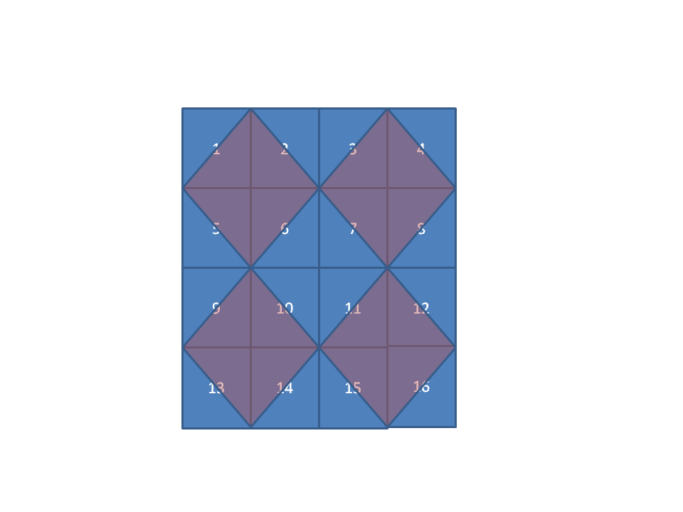
The cross section figure is for a single button, but button replacement designs for multiple buttons placed near each other do not require a one-to-one sensing pad to button. For example, the 4×4 set of buttonscould be implemented with as few as 9 pads by overlapping each touch pad in a diamond shape across up to four buttons. The touch controller can then correlate a touch across multiple pads to a specific button. Touching one of the four corner buttons (1, 4, 13, and 16) requires that only one pad register a touch. To detect a touch on any of the other buttons requires the controller to detect a simultaneous touch on two pads. To support multiple button presses at the same time, the pad configuration would need to add a pad at each corner so that the corner buttons could be uniquely identified.

The next post will discuss touch location detection for touchscreen implementations.

Does and should IT exercise complete control over an embedded developer’s workstation?

Wednesday, October 27th, 2010 by Robert Cravotta

It seems to me everyone has their own personal IT horror stories. I am one of those few people that have lived on both sides of the fence when it comes to running an IT department and doing embedded development. My stint with IT occurred during the transition of combining many independent islands of department networks into a single robust company-wide network.

I enjoyed both jobs. They both had tough challenges, unpredictable and uncontrollable environments, limited budgets, and the end goal of keeping the system operating no matter the failures. I found that the IT team was frustrated at how the users seem bent on purposely destroying the operation of the network while the users were frustrated at how the IT team always tried to prevent them from doing their job. The truth is there were real problems that each side had to solve that the other side didn’t always understand. Worse, each side’s approach often sub-optimized the efforts of the other side.

One strategy that we used to preserve the robustness of the network while allowing the embedded developers the ability to do what they needed with their workstations was to allow them to work in isolated labs. This reduced the variability of hardware and software on the production network without restricting the types of tools the developers could use. However, there were always some on the IT team that did not like this approach because it represented exceptions to the “grand architecture” of the network.

Embedded development is the practice of trade-offs – but then, so is developing a good network design and IT team to keep it running in a productive fashion. Equipment fails all of the time – not because it is of poor quality, but because the equipment runs non-stop every day and the mechanical parts do fail over time. When you consider the thousands of network devices, something is breaking all of the time. To me, it was a system design issue that was similar to the embedded systems I worked on before transferring to the IT group.

Given the horror stories I hear from other embedded developers, maybe our site was not the norm in how we worked with the embedded development teams. Does the IT team find ways to work with your needs or do they force you to work around them like the horror stories seem to indicate. Or are the horror stories merely the result of people embellishing a single bad experience so long ago?

Balancing risk versus innovation – configuration in the design platform

Monday, October 25th, 2010 by Rob Evans

An approach to balance the risk-innovation stalemate is to introduce robust, high-integrity design data management into the electronic design space itself, where it becomes part of the design process, rather than an ‘add-on’ that gets in the way and stifles innovation. This is no trivial task, and needs to be done at the fundamental levels of the design environment, and through all domains. It starts by changing the way the design environment models the process from a collection of disconnected design ‘silos’, to a single concept of product development. In turn, this effectively creates a singular design platform, with the unified data model representing the system being designed.

A platform-based approach offers the possibility of mapping the design data as a single, coherent entity, which simplifies both the management of design data and the process for generating and handing over the data required for procurement and manufacturing. A singular point of contact then exists for all design data management and access, both inside and outside the design environment.

This approach provides a new layer of configuration management that is implemented into the design environment itself, at a platform level. Along with managing the design data, it allows the creation of formal definitions of the links between the design world and the supply chain that is ultimately responsible for building the actual products.

These definitions can be managed as any number of ‘design configurations’. They map the design data, stored as versions of design documents in a nominated repository (a version-controlled design vault), to specific revisions of production Items (blank and assembled boards) that the supply chain is going to build. This formalized management of design data and configurations allows changes to be made without losing historical tracking, or the definitions of what will be made (a design revision) from that version of the design data.

With the design data and configurations under control at a system level, a controlled (or even automated) design release process can potentially eliminate the risks associated with releasing a design to production. This tightly controlled release process extracts design data directly from the design vault, validates, and verifies it with configurable rule checkers, and then generates the outputs as defined by the link definitions. The generated outputs are pushed into a ‘container’ representing a specific revision of the targeted item (typically a board or assembly) that is stored in a design ’release vault’.

In this way all generated outputs, stored as targeted design revisions, are contain in that centralized storage system, where those released for production (as opposed to prototype or ones that may have been abandoned) are locked down and revisioned. It also facilitates support for a simple lifecycle management process that allows the maturity of the revision’s data to be controlled and defined, as well as providing a high-integrity foundation for integration with PLM and PDM systems for those organizations that use them, or plan to.

Such a system supports high-integrity design data management in a platform that allows for productivity and design innovation. This eliminates manual or externally imposed systems that attempt to control design data integrity, along with their associated restrictions in design flexibility and freedom. This system applies to the management of data within the design space, and perhaps more importantly, to the process of releasing the required outputs through to an organization’s supply chain. In practice, it reduces the risk of going to production with a design that was not validated, not in sync, or consists of an incomplete set of manufacturing data.

With formalized, versioned storage ‘vaults’ (for design and release) the system can provide an audit trail that gives you total visibility from the release data back to the source data, even to the level of hour to hour changes to that design information. This coupled with the unique application of configurations to define the links between a design and the various production items to be made, allows design management to become an inherent part of the product development process – as opposed to a constricting system imposed over the top of design.

But most importantly, design can be undertaken without having to give up the flexibility, freedom and creative innovation that’s needed to create the next generation of unique and competitive product designs.

Is it always a software problem?

Wednesday, October 20th, 2010 by Robert Cravotta

When I first started developing embedded software, I ran into an expression that seemed to be the answer for every problem – “It’s a software problem.” At first, this expression drove me crazy because it was blatantly wrong many times, but it was the only expression I ever heard. I never heard it was a hardware problem. If the polarity on a signal was reversed – it was a software problem. If a hardware sensor changed behavior over time – it was a software problem. In short, if it was easier, faster, or cheaper to fix any problem in the system with a change to the software – it was a software problem.

Within a year of working with embedded designs, I accepted the position that any problem that software could provide a fix or limit was defined as a software problem regardless of whether the software did exactly what the design documents specified. I stopped worrying about whether management would think the software developers were inept because in the long run, they seemed to understand that a software problem did not necessarily translate to a software developer problem.

I never experienced this type of culture when I worked on application software. There were clear demarcations between hardware and software problems. Software problems occurred because the code did not capture error return codes or because the code did not handle an unexpected input from the user. A spurious or malfunctioning input device was clearly a hardware problem. A dying power supply was a hardware problem. The developer of the application code was “protected” by a set of valid and invalid operating conditions. Either a key was pressed or it was not. Inputs and operating modes had a hard binary quality to them. At worst, the application code should not act on invalid inputs.

In contrast, many embedded systems need to operate based on continuous real world sensing that does not always translate to obvious true/false conditions. Adding to the complexity, a good sensor reading in one context may indicate a serious problem in a different operating context. In the context of a closed-loop control system, it could be impossible to definitely classify every possible input as good or bad.

Was this culture just in the teams on worked on or is it prevalent in the embedded community? Does it apply to application developers? Is it always a software problem if the software can detect, limit, or fix an undesirable operating condition?

How important are Software Coding Standards?

Wednesday, October 13th, 2010 by Robert Cravotta

When I was developing embedded systems, we had to comply with specifications that would allow a third party to verify the functional behavior of the system. The closest we came to a software coding standard was a short lived mandate that said systems needed to be developed in Ada. Invariably, we always received a waiver to the Ada requirement and generally used C to develop our systems. To be fair, most of what I worked on was prototypes and proof-of-concepts – we typically built a small handful of the system in question. The process for bringing these designs to a manufacturing level was a separate task.

When I started Embedded Insights, I spent some time discussing with my business partner how each of us approached software projects. This was important because we were planning to build a back-end database and client application to deliver capabilities in the Embedded Processing Directory that would change how developers find, research, and select their target processing options. That project is currently ongoing.

One of the software topics we discussed was coding style and how to represent design and implementation decisions. In a sense, we were negotiating software coding standards – but not pretty syntax rules. Rather, we were discussing how each of us incorporated design assumptions into the code so that someone else (possibly even ourselves a few years later) could figure out what thought process drove the software into its current implementation. I believe that is the essence of a coding standard.

Coding standards should not arbitrarily limit implementation decisions. They should enable a third party person to grasp what problems the previous developer was solving. By understanding the different challenges that the developer needed to simultaneously solve, what might appear to be “poor” coding practices might actually be making the best of a difficult situation.

In short, I think a coding standard should provide a mechanism by which developers can encode their assumptions in the implementation code without limiting their choices. This is especially critical for software because software systems must contend with shared resources – most notably in the time domain. The software from each developer must “take turns” using the CPU and other resources.

How important are software coding standards to the projects you work on? Do you use an industry standard or do you have a custom set of conventions that captures the lessons learned of your own “tribe” of developers? How formal are your coding guidelines and how do you enforce them? Or, do you find that spending too much effort on such guidelines contributes more to “mine is better than yours” religious wars than helping the team get the project finished?

Haptic User Interfaces

Tuesday, October 12th, 2010 by Robert Cravotta

Applications that support touch displays overwhelmingly rely on visual feedback to let the user know what touch event occurred. Some applications support delivering an audio signal to the user, such as a click or beep, to acknowledge that a button or virtual key was pressed. However, in many touch interfaces, there is no physical feedback, such as a small vibration, to let the user know that the system detected a touch of the display.

Contrast this with the design of mechanical keyboards. It is an explicit design decision whether the keys are soft or firm to the touch. Likewise, the “noisiness” of the keys and whether there is an audible and physical click at the end of a key press are the result of explicit choices made by the keyboard designer.

As end devices undergo a few design generations of supporting touch interfaces, I expect that many of them will incorporate haptic technology, such as from Immersion, so as to deliver the sensation of the click at the end of a key press. However, I am currently not aware of how a digital touch interface can dynamically simulate different firmness or softness of the touch display, but something like the Impress squishy display may not be too far away.

Some other interesting possibilities for touch based information and feedback are presented in Fabian Hemmert’s video about shape shifting mobile devices. In the video he demonstrates how designers might implement three different types of shape shifting in a mobile phone form factor.

The first concept is a weight-shifting device that can shift its center of mass. Not only could the device provide a tactile feedback of where the user is touching the display, but it can be used to “point” the user in a direction by making it heavier in the direction it wishes to point. This has the potential to allow a device to guide the user through the city without requiring the user to look at the device.

The second concept is a shape-shifting device that can transform from a flat form to one that is raised on any combination of its four corners. This allows the device to extend an edge or taper a corner toward or away from the user to indicate that there is more information in the indicated direction (such as when looking at a map). A shape-shifting capability can also allow the device to be placed on a flat surface, say a nightstand and allow the device to take on a context specific function – say an alarm clock.

The third concept is a “breathing” device where the designer uses the shifting capabilities of the device to indicate a health state of the device. However, to make the breathing concept more than just an energy drain, it will need to be able to decide whether there is someone around to observe it, so that it can save its energy when it is alone.

The mass- and shape-shifting concepts hold a lot of promise, especially when they are combined together in the same device. It might be sooner than we think when these types of features are available to include in touch interfaces.

Software Coding Standards

Friday, October 8th, 2010 by Robert Cravotta

The two primary goals of many software coding standards is to reduce the probability that software developers will introduce errors into their code caused by “poor” coding practices and to make it easier to identify errors or vulnerabilities that make it into a project’s code base. By adopting and enforcing a set of known best practices, coding standards enable software development teams to work together more effectively because they are working from a common set of assumptions. Examples of the types of assumptions that coding standards address are: prohibiting language constructs known to be associated with common runtime errors; specifying when and how compiler or platform-specific constructs may and may not be used; and specifying policies for managing system memory resources such as static and dynamic memory allocation.

Because coding standards involve aligning a team of software developers to a common set of design and implementation assumptions and because every project has its own unique set of requirements and constraints, there is no single, universal best coding standard. Industry-level coding standards center on a given programming language, such as C, C++, and Java. There may be variants for each language based on the target application requirements, such as MISRA-C (Motor Industry Software Reliability Association), CERT C (Computer Emergency Response Team), JSF AV C++ (Joint Strike Fighter), IPA/SEC C (Information-Technology Promotion Agency/ Software Engineering Center), and Netrino C.

MISRA started as a guideline for the use of the C language in vehicle based software, and it has found acceptance in the aerospace, telecom, medical devices, defense, and railway industries. CERT is a secure coding standard that provides rules and recommendations to eliminate insecure coding practices and undefined behaviors that can lead to exploitable vulnerabilities. JSF specifies a safe subset of the C++ language targeting use in air vehicles. The IPA/SEC specifies coding practices to assist in the consistent production of high quality source code independent of an individual programmer’s skill. Netrino is an embedded coding standard targeting the reliability of firmware while also improving the maintainability and portability of embedded software.

Fergus Bolger, CTO at PRQA shares that different industries need to approach software quality from different perspectives – which adds more complexity to the sea of coding standards. For example, aerospace applications exist in a high certification environment. Adopting coding standards is common for aerospace projects where the end system software and the tools that developers use go through a certification process. In contrast, the medical industry takes a more process oriented approach where it is important to understand how the tools are made. MISRA is a common coding standard in the medical community.

At the other end of the spectrum, automotive has an installed automotive software code base that is huge and growing rapidly. Consider that a single high-end automobile can include approximately 200 million lines of code to manage the engine and system safety as well as all of the bells and whistles of the driver interface and infotainment systems. Due to the sheer amount of software, there is less code verification. Each automotive manufacture has their own set of mandatory and advisory rules that they include with the MISRA standard.

A coding standard loses much of its value if it is not consistently adhered to, so a number of companies have developed tools to help with compliance and software checking. The next article will start the process of identifying the players and their approaches to supporting coding standards.

Are you using (or planning to use) Java for programming embedded systems?

Wednesday, October 6th, 2010 by Robert Cravotta

Java is a general-purpose software programming language that features concurrent, class-based, object-oriented constructs that is designed to embody as few implementation dependencies of the target processor as possible. It is a programming language that targets application developers and provides an abstract platform that lets them write their software once and easily run it on many different target processors. Java is a programming language that is used for many mobile device and web applications. But is Java appropriate to meet the trade-offs that embedded developers need to make to build true embedded systems?

Developing application software is different than developing software for embedded systems. I do not think that just because a system is small or resource constrained that it qualifies as an embedded system. Rather, embedded systems are small or resource constrained because they do not lend themselves to extracting a premium from the end user precisely because they are generally invisible to the end user.

While portions of the application code will operate invisibly to the end user, the application software has a real interactive component with the end user. The strength or weakness of that interaction will affect the success or failure of that application code. In contrast, almost all of the software in an embedded system operates invisibly and in an autonomous-like fashion from the end-user.

To clarify, a mobile device, such as a smart phone or a tablet computer, contain both application- and embedded-level software. The application software is what the end user uses and might select and load onto the application processor. For example, the operating system that the target processor supports is often a key consideration, even indirectly from a branding perspective. Apple devices are positioned as “not Microsoft” or “not Windows” devices – even though there are significant similarities in the embedded components of these devices.

The embedded portion of these systems are those parts that the user has no need to know how they are implemented. Examples of the embedded parts of these devices include the wireless network controller and the power management controller. There are many embedded systems even in a desktop computer. The hard disk controller, the network controller, the keyboard and mouse controller, are a few examples. The cooling system and the health checking modules are other examples of embedded systems within the desktop. These are items that how they are implemented does not drive a user’s decision to select that end-system.

At this point, I am not aware of embedded systems as I have identified them here being developed with Java code. Is Embedded Java a marketing meme or is it real? Are you using (or planning to use) Java for your embedded designs? If so, what types of designs are you doing this for?