Man vs. Machine: What’s behind it?

Friday, September 3rd, 2010 by Binay Bajaj

The interaction between ‘man and the machine’ today is very different when compared to 20 – even 10 – years ago. Major changes include how a person interfaces with his everyday consumer device such as a smart phone, notebook, tablet, or navigational device. In the past, a user might push several mechanical buttons to play a handheld game or control household appliances, whereas now, they can use various touch gestures on a screen to play a handheld game, look up directions on a map, read a book on a tablet, or even control the sound of his stereo from a touchscreen.

There have been a number of devices for many years with enhanced functionality but most of these features were not used because it was too complicated. Easy and intuitive interfaces open up a device for the user. Users can quickly discover the power of the device, finding it interactive and enabling them to spend hours on the device, playing with it, and enhancing it by finding new applications.

So what is behind these devices that include intuitive interfaces? What is required to enable these devices to function with such rich user interfaces? The secret is good touch hardware, firmware, as well as the right algorithm and software drivers. These features are all part of a good touch solution that provides design engineers the tools to add touch functionality to various devices.

Many vendors are not ‘end device’ manufacturers; rather, they make the controller and touch solution for OEMs (original equipment manufacturer). These vendors provide a complete touch system so OEMs can implement a feature-rich, intuitive interface in the device for the users. These touch solutions include the touch controller, firmware, touch sensor pattern design, sensor test specification, manufacturing test specification, and software drivers.

However, the OEM needs to do an evaluation of the touch solution at the time of engagement. This is where a sensor evaluation kit showcases the capability of the solution and how the touch solution matches the customer requirement. A software development kit can provide performance characterization, as well as a development platform environment to support various operating systems. A good development kit is easy-to-understand, easy-to-install, and quick.

The software development kit for touch functionality is a key part of the package because it requires the design engineer to install the package himself. Easy-to-use is the key. The vendor provides the hardware and using it may require some collaboration, but the software development kit is typically the challenge for designers. The types of instructions that a touch development kit needs to provide in order to be easy-to-use include how to set-up the board, how to demonstrate the board’s capabilities, and how to configure the software settings.

Vendors understand that the easier it is to use a development kit, the more robust a design engineer can make a product and bring it to market faster. Software development kits make it apparent that the designer can control these various features to offer more touch functionality to the consumers including software algorithms, gestures, lower power, faster response time, and higher accuracy.

Though the interaction between ‘man and the machine’ is changing today, each year brings unlimited possibilities to the market place. The human interface to devices will continue to become easier and support more intuitive interactions between the man and his machine.

When do you use your compiler’s inline assembler feature and for what reasons?

Wednesday, September 1st, 2010 by Robert Cravotta

I am working on a mapping for software that is analogous to the mapping I developed to describe the different types of processing options. The value of this type of mapping is that it improves the visibility as to the assumptions and optimization trade-offs that drive the design and implementation details of a given tool or architecture. A candidate mapping criteria is the coupling between different layers of abstraction between the software and the hardware target. I will be asking questions that try to tease out the assumptions and trade-offs behind the tools you use to move between different layers of abstraction in your designs.

For example, a compiler allows a software developer to write instructions in a high-level language that generally allows the developer to focus on what the software needs to accomplish without having to worry about partitioning and scheduling the execution engine resources such as register reads and writes. For the mapping model, a compiler would have a strong coupling with the high-level language. Additionally, if the developer is using an operating system, the compiler may also support targeting the software to the operating system API (application programming interface) rather than a privileged mode on the target processor. This would constitute another layer of coupling that the compiler must account for.

However, most compilers also include an inline assembler that allows the developer to break these abstraction layers and work at the level of the target processor’s assembly instructions and resources. Using the inline assembler usually means more complexity for the software developer to manage because the compiler is no longer directly controlling some of the target processor’s resources. Using assembly language can also reduce the portability of the software, so developers usually have a good reason to break the abstraction layer and work at the level of the target processor. Reasons for using an inline assembler include improving the execution speed of the software, optimizing the memory usage in the system, and directly controlling special hardware resources in the processor such as co-processors, accelerators, and peripherals.

Under what conditions do you use the inline assembler (or a separate assembler) for you software? What are the project management and technical trade-offs you consider when choosing to work at the assembly level? What features would a compiler need to support that would allow you to avoid using assembly language? Your answers will help refine the software sweet spot mapping that I am currently developing.

Identifying sweet spot assumptions

Monday, August 30th, 2010 by Robert Cravotta

I am continuing to develop a taxonomy to describe the different types of software tools. Rather than waiting until I have a fully fleshed out model, I am sharing my thought process with you in the hopes that it will entice you to share your thoughts and speed up the process of building a workable model.

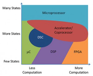
I am offering up the following processing mapping as an example of how an analogous software mapping might look. The mapping identifies two independent characteristics, in this case, the number of states and the amount of computation that the system must handle. One nice thing about mapping the design characteristics like this is that it provides an independence from the target application and allows us to focus on what an architecture is optimizing and why.

For example, a microcontroller’s sweet spot is in the lower end of the computation load but spans from very simple to complicated state machines. Microcontroller architectures emphasize excellent context switching. In contrast, DSP architectures target streaming problems where context switching is less important and maximizing computation for the same amount of time/energy is more important.

I suspect that if we can identify the right characteristics for the axis of the mapping space that software tools will fall into analogous categories of assumptions and optimizations. The largest challenge at this moment is identifying the axes. Candidate characteristics include measures of productivity, efficiency, reusability, abstraction, coupling, and latency tolerance.

An important realization is that the best any software can accomplish is to not stall the hardware processing engine. The software will perform data manipulations and operations that cause the processing engine to stall, or be idle, some percentage of the time. As a result, all software tools are productivity tools that strive to help the developer produce software that is efficient enough to meet the performance, schedule, and budget requirements of the project. This includes operating systems, which provide a layer of abstraction from the underlying hardware implementation.

I propose using a measure of robustness or system resilience and a measure of component coupling as the two axes to map software development tools to a set of assumptions and optimization goals.

The range for the component coupling axis starts at microcode and moves toward higher levels of abstraction such as machine code, assembly code, BIOS, drivers, libraries, operating systems, and virtual machines. Many embedded software developers must be aware of multiple levels of the system in order to extract the required efficiency from the system. As a result, many software tools also target one or more of these layers of abstraction. The more abstraction layers that a tool accommodates, the more difficult it is to build and support.

Consider that while a compiler ideally allows a developer to work at a functional and/or data flow level, it must also be able to provide the developer visibility into the lower level details in case the generated code performs in an unexpected fashion that varies with the hardware implementation. The compiler may include an inline assembler and support #pragma statements that enable the developer to better specify how the compiler can use special resources in the target system.

The robustness axis is harder to define at this moment. The range for the robustness axis should capture the system’s tolerance to errors, inconsistent results, latency, and determinism. My expectation for this axis is to capture the trade-offs that allow the tool to improve the developer’s productivity while still producing results that are “good enough.”  I hope to be able to better define this axis in the next write-up.

Do you have any thoughts on these two axes? What other axes should we consider? The chart can go beyond a simple 2D mapping.

UCSD Turns On the Light on Dark Silicon

Friday, August 27th, 2010 by Max Baron

The session on SoCs at Hot Chips 22 featured only one academic paper among several presentations that combined technical detail with a smidgeon of marketing. Originating from a group of researchers from UCSD and MIT, the presentation titled “GreenDroid: A Mobile Application Processor for a Future of Dark Silicon,” introduced the researchers’ solution to the increase of dark silicon as the fabrication of chips evolves toward smaller semiconductor technology nodes.

The reference to dark silicon seems to have been picked up by the press when in 2009 Mike Muller ARM’s CTO, described the increasing limitations imposed by power consumption, on driving and utilizing the increasing numbers of transistors provided by technology nodes down to 11nm. As described by the media, Mike Muller’s warning spoke about power budgets that could not be increased to keep up with the escalating number of transistors provided by smaller geometries.

Why have power budgets? The word “budget” seems to imply permission that designers can increase power by an arbitrary setting of a higher budget. Carrying power increases to extreme levels however will generate temperatures that will destroy the chip or drastically reduce its lifetime. Thus, a fixed reference die whose power budget is almost fixed due to the die’s fixed dimensions will reach a semiconductor technology node where only a small percent of its Moore’s Law–predicted transistors can be driven. The remaining transistors are the dark silicon.

The solution presented at Hot Chips 22 by UCSD cannot increase the power budget of a SoC but it can employ more dark silicon that would otherwise remain unused. The basic idea was simplicity itself: instead of employing a large power-hungry processor that expends a lot of unnecessary energy in driving logic that may not be needed for a particular application–why not create a large number of very efficient small C-cores (UCSD term) that could execute very short sequences of the application code very efficiently?

Imagine a processor tile such as encountered in MIT’s original design that through further improvement became Tilera’s first tile-configured chip. UCSD is envisioning a similar partition using tiles but the tiles are different. The main and comparatively power-hungry processor of UCSD’s tile is still in place but now, surrounding the processor’s data cache, we see a number of special-purpose compiler-generated C-cores.

According to UCSD, these miniature Tensilica-like or ARC-like workload-optimized ISA cores can execute the short repetitive code common to a few applications more efficiently than the main processor. The main processor in UCSD’s tile – a MIPS engine – still needs to execute the program sequences that will not gain efficiency if they are migrated to C-cores. We don’t know whether the C-cores should be considered coprocessors to the main processor such as might be created by a Critical Blue approach, or slave processors.

UCSD’s presentation did not discuss the limitations imposed by data cache bandwidths on the number of C-cores that by design cannot communicate with one another and must use the cache to share operands and results of computations. Nor did the presentation discuss the performance degradation and delays related to loading instructions in each and every C-core or the expected contention on accessing off-chip memory. We would like to see these details made public after the researchers take the next step in their work.

UCSD did present many charts describing the dark silicon problem plus charts depicting an application of C-cores to Android. A benchmark comparison chart was used to illustrate that the C-core approach could show up to 18x better energy efficiency (13.7x on average). The chart would imply that one could run up to 18x more processing tiles on a dense chip that had large area of dark silicon ready for work, but the presentation did not investigate the resulting performance – we know that in most applications the relationships will not be linear.

I liked the result charts and the ideas but was worried that they were not carried out to the level of a complete SoC plus memory to help find the gotchas in the approach. I was disappointed to see that most of the slides presented by the university reminded me of marketing presentations made by the industry. The academic presentation reminded me once more that some universities are looking to obtain patents and trying to accumulate IP portfolios while their researchers may be positioning their ideas to obtain the next year’s sponsors and later, venture capital for a startup.

What capability is the most important for touch sensing?

Wednesday, August 25th, 2010 by Robert Cravotta

I have been exploring user interfaces, most notably touch sensing interfaces, for a while. As part of this exploration effort, I am engaging in hands-on projects with touch development kits from each of over a dozen companies that offer some sort of touch solution. These kits range from simple button replacement to complex touch screen interfaces. I have noticed, as I work with each kit, that each company chose a different set of priorities to optimize and trade against in their touch solution. Different development kits offer various levels of maturity in how they simplify and abstract the complexity of making a touch interface act as more than just a glorified switch.

It appears there may be a different set of “must have” capabilities in a touch development kit depending on who is using it and for what type of application they are adding it. For button replacement kits, the relevant characteristics seem to focus around cost and robustness with ease of development becoming more important. A common theme among button replacement kits is supporting aggregate buttons, such as a slider bar or wheel, that can act as a single control even though it consists of multiple buttons.

From my perspective, an important capability of a button replacement solution is that it simplifies the initialization and setup of the buttons while still being able to support a wide range of operating configurations. A development kit that offers prebuilt constructs that aggregate the buttons into sliders and wheels are a plus as they greatly simplify the learning curve to use these compound button structures. Another valuable capability is driver software that allows the touch system to detect calibration drift and assists or automates in recalibration. This week’s question asks if these are sufficient leading edge capabilities, or have I missed any important capabilities for button replacement systems?

In contrast, I have noticed that many touch screen solutions focus on multi-touch capabilities. However, I am not convinced that multi-touch is the next greatest thing for touch screens. Rather, I think more high-level abstraction and robust gesture recognition is the killer capability for touch screen solutions. Part of my reasoning for this is the relative importance of “pinching” to zoom and rotate an object versus flicking and tracing to navigate and issue complex commands to the system. The challenges to correctly recognize a zooming and rotating command are somewhat constrained; whereas the challenges to correctly recognize the intended context of a flick or trace gesture are significantly more difficult because there are a wider set of conditions to which a user may apply flick or trace gesture.

As a result, I feel that an important and differentiating capability of a touch screen solution is that it offers prebuilt drivers and filters that are able to consistently identify when a touch gesture is real and intended. It should also be able to accurately differentiate between subtle nuances in a gesture so as to enable the user to communicate a richer set of intended commands to the system. Again, this week’s question seeks to determine if this is the appropriate set of leading edge capabilities, or have I missed any important capabilities for touch screen systems?

Your answers will help direct my hands-on project, and they will help with the database and interface design for the upcoming interactive embedded processing directory.

Clarifying third generation touch sensing

Tuesday, August 24th, 2010 by Robert Cravotta

Eduardo’s response to first and second generation touch sensing provides a nice segue to clarifying third generation touch sensing capabilities. Eduardo said:

One other [classification] that I would say relates to “generations” is the single touch vs multitouch history; which I guess also relates [to] the evolution of algorithms and hardware to scan more electrodes and to interpolate the values between those electrodes. First generation: single touch and single touch matrixes; second generation: two touch, low resolution sliders; third generation: high resolution x-y sensing, multi touch detection.

While there is a “generational” shift between single- and multi-touch sensing, I am not sure the uses for multi-touch commands have reached a tipping point of adoption. My non-scientific survey of what types of multi-touch commands people know how to use yields only zoom and rotate commands. The MSDN library entry for touch provides an indication of the maturity of multi-touch interfaces; it identifies that Windows 7 supports new multi-touch gestures such as pan, zoom, rotate, two-finger tap, as well as press and tap. However, these multi-touch commands are more like manipulations where the “input corresponds directly to how the object would react naturally to the same action in the real world.”

I am excited about the possibilities of multi-touch interfaces, but I think standardizing gesture recognition for movements such as flicks, traces, and drags, which go beyond location and pen up/down data, is the relevant characteristic of third generation touch sensing. Nor is gesture recognition limited to touch interfaces. For example, there are initiatives and modules available that enable applications to recognize mouse gestures. The figures (from the referenced mouse gesture page) highlight a challenge of touch interfaces – how to provide feedback and a means for the user to visually see how to perform the touch command. The figure relies on an optional feature to display a “mouse trail” so that the reader can understand the motion of the gesture. The example figure illustrates a gesture command that combines tracing with a right-up-left gesture to signal to a browser application to open all hyperlinks that the trace crossed in separate tabs.

Open links in tabs (end with Right-Up-Left): Making any gesture ending with a straight Right-Up-Left movement opens all crossed links in tabs.

A common and useful mouse-based gesture that is not yet standard across touch sensing solutions is recognizing a hovering finger or pointer. Several capacitive touch solutions can technically sense a hovering finger, but the software to accomplish this type of detection is currently left to the device and application developer. An important component of detecting a hovering finger is detecting not just where the fingertip is but also what additional part of the display the rest of the finger or pointer is covering so that the application software can place the pop-up or context windows away from the user’s finger.

While some developers will invest the time and resources to add these types of capabilities to their designs today, gesture recognition will not reach a tipping-point until the software to recognize gestures, identify and filter out bad gestures, and abstract the gesture motion into a set of commands finds its way into IP libraries or operating system drivers.

Touchscreen User Interface checklist: criteria for selection

Thursday, August 19th, 2010 by Ville-Veikko Helppi

Touchscreens require more from the UI (user interface) design and development methodologies. To succeed in selecting the right technology, designers should always consider the following important topics.

1) All-inclusive designer toolkit. As the touchscreen changes the UI paradigm, one of the most important aspects of the UI design is how quickly the designer can see the behavior of the UI under development. Ideally, this is achieved when the UI technology contains a design tool that allows the designer to immediately observe behavior of the newly created UI and modify easily before target deployment.

2) Creation of the “wow factor.” It is essential that UI technology enables developers and even end-users to easily create clever little “wow factors” on the touchscreen UI. These technologies, which allow the rapid creation and radical customization of the UI, have a significant impact on the overall user experience.

3) Controlling the BoM (Bill of Material). For UIs, everything is about the look and feel, ease of use, and how well it reveals the capabilities of the device. In some situations, adding a high-resolution screen with a low-end processor is all that’s required to deliver a compelling user experience. Equally important is how the selected UI technology reduces engineering costs related to UI work. Adapting a novel technology that enables the separation of software and UI creation enables greater user experiences without raising the BoM.

4) Code-free customization. Ideally, all visual and interactive aspects of a UI should be configurable without recompiling the software. This can be achieved by providing mechanisms to describe the UI’s characteristics in a declarative way. Such a capability affords rapid customization without any changes to the underlying embedded code base.

5) Open standard multimedia support. In order to enable the rapid integration of any type of multimedia content into a product’s UI (regardless of the target hardware) some form of API standardization must be in place. The OpenMAX standard addresses this need by providing a framework for integrating multimedia software components from different sources, making it easier to exploit silicon-specific features, such as video acceleration.

Just recently, Apple replaced Microsoft as the world’s largest technology company. This is a good example of how a company that produces innovative, user-friendly products with compelling user interfaces can fuel the growth of technology into new areas. Remember, the key isn’t necessarily the touchscreen itself – but the user interfaces running on the touchscreen. Let’s see what the vertical markets can do to take the user interface and touchscreen technology to the next level!

Can we improve traffic safety and efficiency by eliminating traffic lights?

Wednesday, August 18th, 2010 by Robert Cravotta

I love uncovering situations where there is a mismatch between the expected results and the actual results of an experiment because it helps reinforce the importance of actually performing an experiment despite how much you think you “know” how it will turn out. System level integration of the software with the hardware is a perfect example.

It seems, with a frequency that defies pure probability, that if the integration team fails to check out an operational scenario during integration and testing, the system will behave in an unexpected manner when that scenario occurs. Take for example Apple’s recent antenna experience:

“…The electronics giant kept such a shroud of secrecy over the iPhone 4′s development that the device didn’t get the kind of real-world testing that would have exposed such problems in phones by other manufacturers, said people familiar with the matter.

The iPhones Apple sends to its carrier partners for testing are “stealth” phones that disguise a new device’s shape and some of its functions, people familiar with the matter said. Those test phones are specifically designed so the phone can’t be touched, which made it hard to catch the iPhone 4′s antenna problem. …”

The prototype units did not operate under the same conditions as they would in a production capacity, and that allowed an undesirable behavior to get through to the production version. The message here is never assume your system will work the way you expect it to – test it because the results may just surprise you.

Two recent video articles about removing traffic lights from intersections support this sentiment. In one of the video interviews a traffic specialist that suggests that turning off the traffic lights at intersections can actually improve the safety and efficiency of some intersections. The other video highlights what happened when a town turned off the traffic lights at a specific intersection. The results are anti-intuitive. This third video of an intersection is fun to watch, especially when you realize that there is no traffic control and there are all types of traffic, ranging from pedestrians, bikes, small cars, large cars, and buses all sharing the road. I am amazed watching the pedestrians and the near misses that do not appear to faze them.

I am not advocating that we turn off traffic lights, but I am advocating that we explore whether we are testing our assumptions sufficiently – whether in our own embedded designs or in other systems including traffic control. What is causing better traffic flow and safety in these test cases? Is it because the flow is low enough? Is it because the people using the intersection are using a better set of rules rather than “green means go?” Are there any parallel lessons learned that apply to integrating and testing embedded systems?

Software Ecosystem Sweet Spots

Monday, August 16th, 2010 by Robert Cravotta

I have been refining a sweet spot taxonomy for processors and multiprocessing designs for the past few years. This taxonomy highlights the different operating assumptions for each type of processor architecture including microcontrollers, microprocessors, digital signal processors, hardware accelerators, and processing fabrics.

I recently started to focus on developing a similar taxonomy to describe the embedded software development ecosystem that encompasses the different types of tools and work products that affect embedded software developers. I believe developing a taxonomy that identifies the sweet spot for each type of software component in the ecosystem will enable developers and tool providers to better describe the assumptions behind each type of software development tool and how to evolve them to compensate for the escalating complexity facing embedded software developers.

The growing complexity facing software developers manifests in several ways. One source of the growing complexity is the increase in the amount of code that exists in designs. The larger the amount of code within a system, the more there are opportunities for unintended resource dependencies that affect the performance and correct operation of the overall system. Using a modular design approach is a technique to manage some of this complexity, but modular design works to abstract the resource usage within a module and does not directly affect how to manage the memory and timing resources that the modules share with each other by virtue of executing on the same processor.

Another source of growing complexity is “path-finding” implementations of new functions and algorithms because many algorithms and approaches for solving a problem are first implemented as software. New algorithms undergo an evolution as the assumptions in the specification and coding implementation of the algorithms operate under wider range of operating conditions. It is not until the implementation of those algorithms matures, by being used across a wide enough range of operating conditions, that it makes sense to implement hardened and optimized versions using coprocessors, accelerators, and specialized logic blocks.

According to many conversations I have had over the years, the software in most embedded designs consumes more than half of the development budget; this ratio holds true even for “pure” hardware products such as microcontrollers and microprocessors. Consider that no company releases contemporary processor architectures anymore without also providing significant software assets that include tools, intellectual property, and bundled software. The bundled software is necessary to ease the learning curve for developers to use the new processors and to get their designs to market in a reasonable amount of time.

The software ecosystem taxonomy will map all types of software tools including assembler/compilers, debuggers, profilers, static and dynamic analyzers, as well as design exploration and optimization tools to a set of assumptions that may abstract to a small set of sweet spots. It is my hope that applying such a taxonomy will make it easier to understand how different software development tools overlap and complement each other, and how to evolve the capabilities of each tool to improve the productivity of developers. I think we are close to the point of diminishing returns of making compilation and debugging faster; rather, we need more tools that understand system level constructs and support more exploration – otherwise the continuously growing complexity of new designs will negatively impact the productivity of embedded software developers in an increasingly meaningful manner.

Please contact me if you would like to contribute any ideas on how to describe the assumptions and optimization goals behind each type of software development tool.

Who Will Make the Digital Health System?

Friday, August 13th, 2010 by Max Baron

Until a few days ago, I was asking myself how Intel would transfer results of its research to system manufacturers. I was wondering about the strategy Intel might use to turn the Digital Health system into a real product that could sell to tens of millions of people. Will the company become a paid system IP provider in addition to its semiconductor business, or will it offer the accumulated system expertise free of charge just to generate more sockets for its processors? Intel’s strategy could indicate to us one way in which the company might transfer ideas coming from its freshly announced Interaction and Experience Research (IXR) group to potential OEMs.

The Digital Health system has not been totally dormant. It has seen some adoption although mainly abroad, but compared with products such as the desktop PC, or even the relatively new netbook, Digital Health has remained practically a prototype.

But, to go back to my question, it’s not just about who will fabricate and market the Digital Health system. There are other important details to learn such as who will develop the hardware and software and what will be the business strategy needed to equip the system with medical peripherals that can be deployed at home? These questions have remained unanswered until a few days ago when we learned at least one of the many possible answers.

Intel will transfer the development and marketing of the Digital Health system to . . . Intel and GE or more precisely to a separate company jointly owned by the two partners.

The joint announcement by the two companies answered some of the original questions but left most of the details to be communicated at a later time. We know for instance that the two partners will each provide 50% of the funding for the joint venture and we can assume that they will share profits in the same way. We know that the partnership has created a fully owned company. The two partners have not yet selected a name for the company but they have communicated that Louis Burns, V.P. and general manager of Intel’s Digital Health Group, will be CEO of the new company, and Omar Ishrak, senior V.P. of GE and president and CEO of GE’s Healthcare Systems, will be the chairman of the board.

The partnership seems to be a perfect match. General Electric has developed and continues to design health-care monitoring instrumentation but it needs a processor system to provide the required user-patient interface and the communication to the doctor at the clinic. Intel’s Digital Health system can provide the user-interface, the control and the communications but, it needs the additional medical peripherals that can turn it into a complete health care system.

The new company has evolved from an earlier alliance announced in 2009 according to which Intel and GE would invest $250 million over five years in marketing and developing home-based health technologies targeting seniors living independently and patients with chronic conditions to help manage their care from the comfort of their home.

The 2009 alliance, which had GE Healthcare sell and market the Intel Health Guide–a care management tool– has thus blossomed into a new well-funded startup and for good reason: at the time, according to a GE press release, Datamonitor reported that the market for US and Europe telehealth care was predicted to grow from $3 billion in 2009 to an estimated $7.7 billion by 2012.

I’m optimistically translating the forecast to imply that in 2012 the market will see shipments of approximately 6.16 million units priced at an average of $1,250 in the US and Europe. The worldwide number could come close to 10 million processors if we think in terms of chips—that’s not much for the semiconductor giant that sells hundreds of millions of chips annually—but very promising for an OEM business.

If the rapid growth of the health care at home market materializes as predicted one year ago, it will offer opportunities for more semiconductor companies such as Analog devices, Freescale, Microchip, Renesas, STMicroelectronics, Texas Instruments, and many others that can provide inexpensive microcontrollers, hybrid MCU/DSPs, AD and DA converters plus semiconductor transducers such as accelerometers, gyros, and capacitive, resistive, temperature and pressure sensors (reference: Embedded Processing Directory). According to a Q&A session held a few days ago, Intel and GE’s still-to-be-named company will develop all of the needed technologies internally including all of the needed hardware and software—a statement that if taken literally may involve hundreds of employee experts in different technical disciplines. However, we should not be surprised if some of the related work is contracted out to other companies.

Having learned the answers to a few macro questions, we should ask questions at the next level of detail: will the new system employ a standard operating system and if true, how will it keep up with the innumerable updates – security and bug fixes—that we see coming over the Internet today – irrespective of the operating system software vendor?

How will it protect the security of health-sensitive information? Who will be creating and maintaining the software needed to run on the medical clinic servers – software that needs to communicate with the patient, access the patient’s database, interface with the doctor, and even make some simple decisions by itself?

Will non -GE or -Intel makers of medical peripherals be supported by appropriate hardware and software open standards allowing them to extend and improve the system? Once the opportunity in remote health care is proven, which other manufacturers and alliances already looking at it now will compete with Intel and GE? Will the cellphone take advantage of the opportunity? Will Intel and GE also create a system that involves a cellphone?

The Digital Health system is an important innovation in health care that can improve the quality of life for millions of users and reduce the cost of delivering it. Its implementation will also provide a lesson in complex system design that combines analog and digital embedded peripherals with advanced user interfaces, PC-like execution applications, and Wi-Fi and Internet communication with advanced software running on servers.