Considerations for 4-bit processing

Friday, December 10th, 2010 by Robert Cravotta

I recently posed a question of the week about who is using 4-bit processors and for what types of systems. At the same time, I contacted some of the companies that still offer 4-bit processors. In addition to the three companies that I identified as still offering 4-bit processors (Atmel, EM Microelectronics, and Epson), a few readers mentioned parts from NEC Electronics, Renesas, Samsung, and National. NEC Electronics and Renesas merged and Renesas Electronics America now sells the combined set of those company’s processor offerings.

These companies do not sell their 4-bit processors to the public developer community in the same way that 8-, 16-, and 32-bit processors are. Atmel and Epson told me their 4-bit lines support legacy systems. The Epson lines support most notably timepiece designs. I was able to speak with EM Microelectronics at length about their 4-bit processors and gained the following insights.

Programming 4-bit processors is performed in assembly language only. In fact, the development tools cost in the range of $10,000 and the company loans the tools to their developer clients rather than sell them. 4-bit processors are made for dedicated high volume products – such as the Gillette Fusion ProGlide. The 4-bit processors from EM Microelectronics are available only as ROM-based devices, and this somewhat limits the number of designs the company will support because the process to verify the mask sets is labor intensive. The company finds the designers that can make use of these processors – not the other way around. The company approaches a developer and works to demonstrate how the 4-bit device can provide differentiation to the developer’s design and end product.

The sweet spot for 4-bit processor designs are single battery applications that have a 10 year lifespan and where the device is active perhaps 1% of that time and in standby the other 99%. An interesting differentiator for 4-bit processors is that they can operate at 0.6V. This is a substantial advantage over the lowest power 8-bit processors which are still fighting over the 0.9 to 1.8V space. Also, 4-bit processors have been supporting energy harvesting designs since 1990 whereas 8- and 16-bit processor vendors are only within the last year or so beginning to offer development and demonstration kits for energy harvesting. These last two revelations strengthen my claim in “How low can 32-bit processors go” that smaller sized processors will reach lower price and energy thresholds years before the larger processors can feasibly support those same thresholds – and that time advantage is huge.

I speculate that there may be other 4-bit designs out there, but the people using them do not want anyone else to know about them. Think about it, would you want your competitor to know you were able to simplify the problem set to fit on such a small device? Let them think you are using a larger, more expensive (cost and energy) device and wonder how you are doing it.

What feature would you most like embedded designs to enable in systems you use?

Wednesday, December 8th, 2010 by Robert Cravotta

I remember the first time I heard about keyless entry on an automobile. I thought it was the most frivolous idea ever – that is, until I started using a car with said feature. The thing is, keyless entry and operation is not a feature that enables you to perform some new maneuver or drive further than before – rather it is a harbinger of a new class of features that rely on systems to be smarter and able to “infer the user’s intent” without explicitly using keyholes or data entry devices.

The wireless communication that takes place between the automobile and the key carried by the user enables an invisible interface between the user and the automobile. The automobile can act as if it recognizes the user and act accordingly. A user does not carry a recognized key, they cannot unlock or operate the automobile. Additionally, if the car is in an operating state and all authorized keys move out of range, the car notices this, notifies the operator, and can shut the vehicle down if a key is not brought back in range to the automobile. I experienced this when my wife drove the car up to the driveway, left the car running, and I pulled it into the garage, but I did not have my key on me and the car warned me about not being able to detect an authorized key.

When a user, carrying a recognized key approaches the automobile, the car senses the key and can begin to perform functions that make using the car simpler. For example, when I approach my car it turns on some lights on the door I am approaching; this makes it easier to see when it is dark and signals to me that the car recognizes me. There are other features in the car that turn on and off automagically that I like, such as automatic windshield wipers. Each of these features incorporates more smarts than manual systems and do a good enough job that they remove the cognitive load for managing those functions of the car from the operator.

One thing I like about these types of features is that they are embedded systems made visible. They often do not require the user to adjust to the system because one of their primary purposes is to adjust to the operator and infer the operator’s intent with significant accuracy. Designed correctly, the average user might never think about these types of features. They embodied the essence of an embedded system – invisible but indispensible to the proper operation of the system.

Do you have any examples of features that either exist or that you would like to see added to devices or systems? One thing I now would like to see is a cost effective way to make my house as smart as my car and let me in without requiring me to take the house key out and manually unlock the door. What ideas do you have?

The importance of failing quickly and often

Friday, December 3rd, 2010 by Robert Cravotta

When do recent graduates of kindergarteners outperform recent graduates of business school? Believe it or not, according to Tom Wujec, kindergarteners consistently perform better than business school graduates in the Marshmallow Challenge. This is not a challenge to see who can eat the most marshmallows; rather, it is an exercise in teamwork and rapid prototyping.

The challenge consists of a team of four members building the tallest structure they can using only a single marshmallow, strands of dry spaghetti, a roll of masking tape, and some string. The major constraint is that the marshmallow must go on the top of the structure. The mass of the marshmallow makes this project more challenging than you might first assume.

In Tom’s video, he explains that kindergarteners do better than the business school graduates because they approach the process of building the structure in a more iterative and prototyping sequence than do the business graduates. The kindergarteners start building and placing the marshmallow at the top of the structure right away and they receive immediate feedback from when the structure stands or falls that enables them to make improvements in the next attempt. In contrast, the business graduates discuss a plan of action, choose a direction, and typically do not place the marshmallow on the top of the structure until near the end of the challenge, and when the structure fails, there is not enough time to perform another iteration of rebuilding the structure.

I bring up the Marshmallow Challenge because it augments Casey Weltzin’s recent article “To Design Innovative Products, You Must Fail Quickly” about the importance of prototyping and the role of failures during the prototyping process. Engineers are intimately familiar with failure – in fact, I remember there was a unit on errors and failure as part of my engineering undergraduate studies. Not surprisingly, the people who consistently do the best in the challenge are engineers and architects.

The unrelenting and almost predictable pace of technological improvements that engineers deliver decade after decade belies the amount of failures that engineers experience and iterate through behind each of those publicly visible successes. In a sense, our repeated success as an industry to deliver ever more functional systems at a low price point engenders a sense that it is easier than it truly is to perform these feats of innovation over and over again.

Another interesting observation in Tom’s presentation is that adding an executive admin to a team of CEOs and company executives significantly improves their performance in the challenge than the team without an admin. One take away I see from this is that it is important to be able to expose and remind your management that design is an iterative process where we apply our assumptions to the real world and the real world smacks us down by pointing out our hidden or unspoken assumptions that do not quite align with reality.

What is your favorite debugging anecdote?

Wednesday, December 1st, 2010 by Robert Cravotta

We all know stories about how something went wrong during a project and how we or someone else was able to make a leap of logic that enabled them to solve the problem. However, I think the stories that stick with us through the years are the ones that imparted a longer term insight that goes beyond the actual problem we were trying to solve at the time. For example, I have shared two such stories from my days as a junior member of the technical staff.

One story centers around solving an intermittent problem that ultimately would have been completely avoided if the development team had been using a more robust version control process. The other story involves uncovering an unexpected behavior in a vision sensor that was uncovered only because the two junior engineers that were working with the sensor were encouraged to think beyond the immediate task they were assigned to do.

More than twenty years later, these two stories still leave me with two key insights that I find valuable to pass on to other people. In the version control story, I learned that robustness is not just doing things correctly, but involves implementing processes and mechanisms to be able to automatically self-audit the system. Ronald Reagan’s saying “Trust but verify” is true on so many levels. In the valuing uncertainty story, I learned that providing an appropriate amount of wiggle room in work assignments is an essential ingredient to creating opportunities to grow your team member’s skills and experience while improving the performance of the team.

I suspect we all have analogous stories and that when we share them with each other, we scale the value of our lessons learned that much more quickly. Do you have a memorable debugging anecdote? What was the key insight(s) you got out of it? Is it a story that grows in value and is worth passing on to other members in the embedded community? I look forward to seeing your story.

Are you, or would you consider, using a 4-bit microcontroller?

Wednesday, November 24th, 2010 by Robert Cravotta

Jack Ganssle recently asked me about 4-bit microcontrollers. He noted that there are no obvious 4-bit microcontrollers listed in the Embedded Processing Directory – but that is partly because there are so few of them that I “upgraded” them to the 8-bit listing a few years back. In all the years I have been doing the directory, this is the first time someone has asked about the 4-bitters.

I suspect the timing of Jack’s inquiry is related to his recent article “8 bits is dead” where he points out that the predicted death of 8-bit microcontrollers continues to be false – in fact, he predicts “that the golden age of 8 bits has not yet arisen. As prices head to zero, volumes will soar putting today’s numbers to shame.” I agree with him, the small end of the processing spectrum is loaded with potential and excitement, so much so that I started a series on extreme processing thresholds a few months ago to help define where the current state of the art for processing options is so that it is easier to identify when and how it shifts.

The timing of this inquiry also coincides with Axel Streicher’s article asking “Who said 16-bit is dead?” Axel makes a similar observation about 16-bit processors. I would have liked to have seen him point out that 16-bit architectures is also a sweet spot for DSC (digital signal controllers), especially because Freescale was one of the first companies to adopt the DSC naming. A DSC is a hybrid that combines architectural features of a microcontroller and a digital signal processor in a single execution engine.

A comment on Jack’s article suggested that this topic is the result of someone needing a topic for a deadline, but I beg to differ. There are changes in the processing market that constantly raise the question of whether 8- and 16-bitters will finally become extinct. The big change this year was the introduction of the Cortex-M0 – and this provided the impetus for me to revisit this same topic, albeit from a slightly different perspective, earlier this year when I asked “How low can 32 bits processors go?” I offer that a key advantage that smaller processors have over 32-bit processors is that they reach lower cost and energy thresholds several years before 32-bit processors can get there, so the exciting new stuff will be done on the smaller processors long before they are put on a 32-bit processor.

In contrast, the humble 4-bit gets even less to no attention than the 8- and 16-bitters – but the 4-bit microcontroller is not dead either. Epson just posted a new data sheet for a 4-bit microcontroller a few weeks ago (I am working to get them added to the Embedded Processing Directory now). The Epson 4-bitters are legacy devices that are used in time pieces. EM Microelectronics’ EM6607 is a 4-bit microcontroller; I currently have a call to them to clarify its status and find out what types of applications it is used in.You can still find information about Atmel’s MARC4 which the company manages out of their German offices and is not currently investing any new money into.

So to answer Jack’s question – no, 4-bit processors are not dead yet, and they might not die anytime soon. Are any of you using 4-bit processors in any shape or form? Would you consider using them? What types of processing characteristics define a 4-bitter’s sweet spot? Do you know of any other companies offering 4-bit processors or IP?

Capacitive button sense algorithm

Tuesday, November 23rd, 2010 by Robert Cravotta

There are many ways to use capacitive touch for user interfaces; one of the most visible ways is via a touch screen. An emerging use for capacitive touch in prototype devices is to sense the user’s finger on the backside or side of the device. Replacing mechanical buttons is another “low hanging fruit” for capacitive touch sensors. Depending on how the touch sensor is implemented, the application code may be responsible for working with low level sensing algorithms, or it may be able to take advantage of higher levels of abstraction when the touch use cases are well understood.

The Freescale TSSEVB provides a platform for developers to work with capacitive buttons placed in slider, rotary, and multiplexed configurations. (courtesyFreescale)

Freescale’s Xtrinsic TSS (touch sensing software) library and evaluation board provides an example platform for building touch sensing into a design using low- and mid-level routines. The evaluation board (shown in the figure) provides electrodes in a variety of configuration including multiplexed buttons, LED backlit buttons, different sized buttons, and buttons grouped together to form slider, rotary, and keypad configurations. The Xtrinsic TSS supports 8- and 32-bit processors (the S08 and Coldfire V1 processor families), and the evaluation board uses an 8-bit MC9S08LG32 processor for the application programming. The board includes a separate MC9S08JM60 communication processor that acts as a bridge between the application and the developer’s workstation. The evaluation board also includes an on-board display.

The TSS library supports up to 64 electrodes. The image of the evaluation board highlights some of the ways to configure electrodes to maximize functionality while using fewer electrodes. For example, the 12 button keypad uses 10 electrodes (numbered around the edge of the keypad) to detect the 12 different possible button positions. Using 10 electrodes allows the system to detect multiple simultaneous button presses. If you could guarantee that only one button would be pressed at a time, you could reduce the number of electrodes to 8 by eliminating the two small corner electrodes numbered 2 and 10 in the image. Further in the background of the image are four buttons with LEDs in the middle as well as a rotary and slider bar.

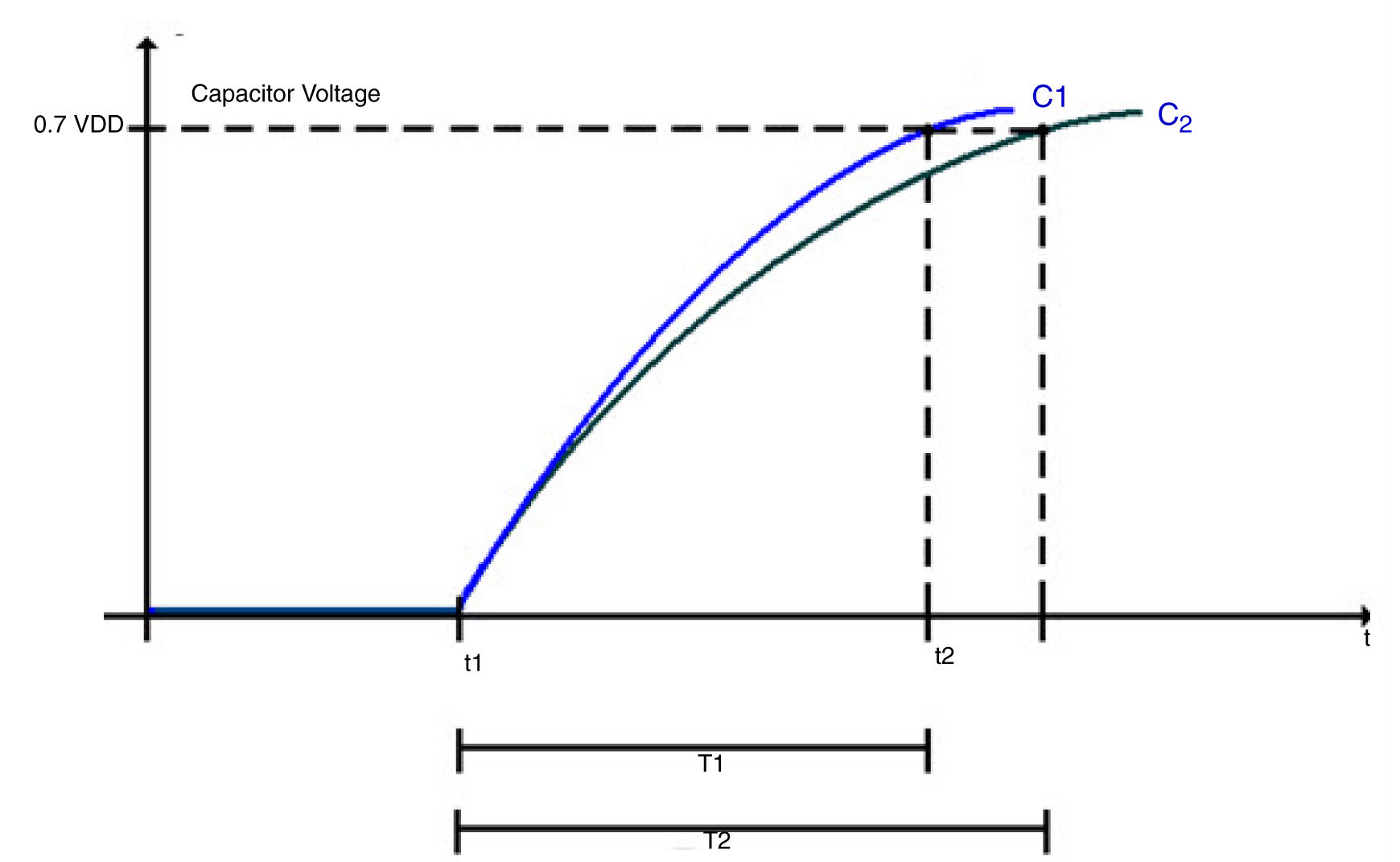
The charge time of the sensing electrode is extended by the additional capacitance of a finger touching the sensor area.

Each electrode in the touch sensing system acts like a capacitor with a charging time defined as T = RC. An external pull-up resistor limits the current to charge the electrode which in turn affects the charging time. Additionally, the presence or lack of a user’s finger near the electrode affects the capacitance of the electrode which also affects the charging time.

In the figure, C1 is the charging curve and T1 is the time to charge the electrode to VDD when there is no extra capacitance at the electrode (no finger present). C2 is the charging curve and T2 is the time to charge the electrode when there is extra capacitance at the electrode (finger present).The basic sensing algorithm relies on noting the time difference between T1 and T2 to determine if there is a touch or not.

The TSSEVB supports three different ways to control and measure the electrode: GPIO, the KBI or pin interrupts, and timer input capture. In each case, the electrode defaults to an output high state. To start measuring, the system sets the electrode pins output low to discharge the capacitor. By setting the electrode pin to a high impedance state, the capacitor will start charging. The different measurement implementations set and measure the electrode state slightly differently, but the algorithm is functionally the same.

The algorithm to detect a touch consists of 1) starting a hardware timer; 2) starting the electrode charging; 3) waiting for the electrode to charge (or a timeout to occur); and 4) returning the value of the timer. One difference between the different modes is whether the processor is looping (GPIO and timer input capture) or in a wait state (KBI or pin interrupt) which can affect whether you can perform any other tasks during the sensing.

There are three parameters which will affect the performance of the TSS library: the timer frequency, the pull-up resistor value, and the system power voltage. The timer frequency affects the minimum capacitance measurable. The system power voltage and pull-resistor affect the voltage trip point and how quickly the electrode charges. The library uses at least one hardware timer, so the system clock frequency affects the ability of the system to detect a touch because the frequency affects the minimum capacitance value detected per timer count.

The higher clock the frequency, the smaller the amount of capacitance the system can detect. If the clock rate is too fast for the charging time, the timer can overflow. If the clock rate is too slow, the system will be more susceptible to noise and have a harder time reliably detecting a touch. When I was first working with the TSSEVB, we chose less than optimally values and the touch sensing did not work very well. After figuring out there was a mismatch in the scaling value that we chose, the performance of the touch sensing drastically improved.

The library supports what Freescale calls Turbo Sensing, which is an alternative technique to measure charge time by counting bus ticks instead of using a timer. This increases the system integration flexibility and makes measurement faster with less noise and supports interrupt conversions. We did not have time to try out the turbo sensing method.

The decoder functions, such as for the keypad, slider, or rotary configurations, support a higher level of abstraction to the application code. For example, the keypad configuration relies on each button mapping to two electrodes charging at the same time. As an example, in the figure, the button numbered 5 requires electrodes 5 and 8 to charge together as each of those electrodes covers half of the 5 button. The rotary decoder handles more information than the key press decoder because it not only detects when electrode pads have been pressed, but it reports from what direction (of two possibilities) the pad was touched and how many pads experienced some displacement. This allows the application code to control the direction and speed of moving through a list. The slider decoder is similar to the rotary decoder except that the ends of the slider do not touch each other.

The size and shape of each electrode pad, as well as the parameters mentioned before, affects the charging time, so the delta in the T1 and T2 times will not necessarily be the same for each button. The charging time for each electrode pad might change as environmental conditions change. However, because detecting a touch is based on a relative difference in the charging time for each electrode, the system provides some resilience to environmental changes.

‘DRM’ For Systems: Protecting Data and Engineering Intellectual Property

Friday, November 19th, 2010 by Max Baron

Freescale Semiconductor has just launched a low cost chip that can be used to protect network-connected low power systems from unauthorized access to system-internal resources. Freescale’s target: a chip that can secure the growing number of network endpoints.

When it comes to e-books, images, music, TV episodes and movies, the authors’ and producer’s rights are protected by encryption. Encryption makes it impossible to easily and legally take on trips or vacations any literature or multimedia from the device to which these have been originally attached. Further, it makes it impossible to create important backups since optical, magnetic and flash memory media can lose part of their content more easily than books or film.

Priceless art in its different forms must be protected. If however we separate the unique talent and genius from the money and time invested, we find that DRM (Digital Rights Management) protects investments ranging from a few tens of thousands of dollars to the sometimes high cost of two-three hundred million dollars per movie (exception: the cost of Avatar was estimated at $500M).

Yet, nobody protects the brainchildren of system architects, software and hardware engineers and the investments and hard work that have produced the very systems that made feasible the art and the level of civilization we enjoy today. They are not protected by a DRM where “D” stands for “Designers.”  Separating priceless engineering genius and talent from investment, we find similar sums of money invested in hardware and software aside from the value of sensitive data in all its forms that can be stolen from unprotected systems.

Freescale Semiconductor’s recent introduction is adding two new members to the QorIQ product family (QorIQ is pronounced ‘coreIQ’). They are the company’s Trust Architecture-equipped QorIQ P1010 and the less featured QorIQ P1014. The QorIQ P1010 is designed to protect factory equipment, digital video recorders, low cost SOHO routers, network-attached storage and other applications that would otherwise present vulnerable network endpoints to copiers of system HW and SW intellectual property, data thieves and malefactors. 

It’s difficult to estimate the number of systems that have been penetrated analyzed and/or cloned by competitors or modified to offer easy access to data thieves, but some indirect losses that have been published can be used to understand the problem.

In its December 2008 issue, WIRED noted that according to the FBI, hackers and corrupt insiders have stolen since 2005 more than 140 million records from US banks and other companies, accounting each year for a loss of $67 billion. The loss was owed to several factors.  In a publication dated January 19, 2006, c-net discusses the results of an FBI-research involving 2,066 US organizations out of which 1,324 have suffered losses over a 12-month period from computer-security problems. Respondents spent nearly $12 million to deal with virus-type incidents, $3.2 million on theft, $2.8 million on financial fraud, and $2.7 million on network intrusions. The last number represents mostly system end-user loss since it’s difficult to estimate the annual damage to the system and software companies that have created the equipment. 

Freescale Semiconductor’s new chip offers a two-phase secure access to the internals of network-connected low cost systems. The first phase accepts passwords and checks the authorization of the requesting agent be it a person or machine. The second phase provides access to the system’s HW and SW internals if the correct passwords have been submitted.

Fabricated in 45nm SOI, Freescale Semiconductor’s QorIQ P1010 shown in the Figure is configured around an e500 core — a next generation core that’s downward code-compatible with the e300 core that populates the company’s PowerQUICC II Pro communications processors. QorIQ P1010’s Power Architecture e500 core is designed to be clocked at up to 800MHz and is estimated by Freescale Semiconductor to consume in some applications less than 1.1W.

The chip’s single e500 core configuration follows the same concept employed in Freescale Semiconductor’s higher performance QorIQ chip family where protected operating system and applications are executed by multiple e500 cores at higher frequencies. The common configuration has the family’s processing cores and supporting cache levels surrounded by application-specific high bandwidth peripherals that include communication with the network, system-local resources and system-external peripherals.

External peripherals such as cameras will be encountered by the QorIQ P1010 in digital video recorders (DVR) accepting analog video streams from surveillance cameras. The DVRs may employ local storage for locally digitized and encoded video and/or make use of a network to access higher capacity storage and additional processing.

FlexCAN interfaces are the most recent on-chip application-specific peripherals encountered in the QorIQ P1010. The chips’ architects and marketing experts are probably responding to requests coming from potential customers building factory equipment. Aside from e500 cores and peripherals, the denominator common to most chips in the family is the little documented Trust Architecture.

An approximate idea of the Trust Architecture’s internals and potential can be gleaned from a variety of documents and presentations made by Freescale Semiconductor, from ARM’s Cortex-A series of cores employing a similar approach under that company’s brand named “TrustZone,” and from today’s microcontroller technologies used in the protection of smart cards.

The basic components of a secure system must defend the system whether it’s connected to the network or not, under power or turned off, monitored externally or probed for activity.

In the QorIQ P1010’s configuration of the first phase we should expect to find encrypt-decrypt accelerators used in secure communication with off-chip resources and on-chip resident ROM. The content of these resources should be inaccessible to any means that don’t have access to the decryption keys.

Off-chip resources could include system-internal such as SDRAM, Flash memory, optical drives and hard drives. Examples of system-external resources can be desktops, network attached storage, and local or remote servers.

The on-chip resident ROM probably contains the code-encrypted security monitor and boot sequence. A set of security fuses may be used to provide the necessary encryption-decryption keys. Different encryption-decryption keys defined for different systems would tend to limit damage made by malefactors but in case of failure could render encrypted data useless unless the same keys could be used in a duplicate system. Keys implemented in 256 bits or higher will make it very difficult in time and money to break into the system.
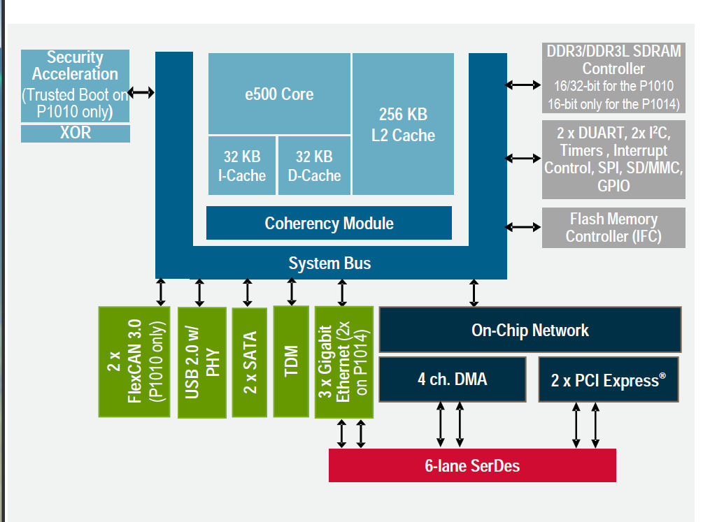
The block diagram of the QorIQ P1010 shows the peripherals incorporated on-chip but understandably offers less information about the Trust Architecture protecting the SoC. The QorIQ P1014 should cost less and should be easier to export since it lacks the Trust Architecture and shows a more modest set of peripherals. (Courtesy of Freescale Semiconductor)

Initial system bring-up, system debug and upgrade processes require access to chip internals. According to Freescale Semiconductor the chip’s customers will be provided with a choice among three modes of protected access via JTAG: open access until the customer locks it, access locking w/o notification after a period allowing access for debug, and JTAG delivered as permanently closed w/o access.  Customers also have the option to access internals via the chip’s implementation of the Trust Architecture.

Tamper detection is one of the most important components in keeping a secure chip from unauthorized analysis. Smart cards detect tampering in various ways: they monitor voltage, die temperature, light, bus probing, and in some implementations, also employ a metal screen to protect the die from probing. We should assume that the system engineer can use the QorIQ P1010 to monitor external sensors through general purpose input/outputs protecting the system against tampering — to ensure that the system will behave as the intended by the original manufacturer.

 The QorIQ P1010’s usefulness depends on the system configuration using it.  A “uni-chip” system will be protected if it incorporates hardwired peripherals such as data converters and compressors, but it employs only the QorIQ P1010 for all its programmable processing functions. According to Freescale Semiconductor’s experts, a system’s data communications with other systems on the network will be protected if the other systems also employ the QorIQ P1010 or other members of the QorIQ chip family. Simple systems of this kind can use the QorIQ P1010 to protect valuable system software and stored data since except in proprietary custom designs the hardware may be easy to duplicate.

Note that systems employing the QorIQ P1010 plus additional programmable SoCs are more vulnerable.

Freescale has not yet announced the price of the QorIQ P1010. To gain market share the difference in cost of the QorIQ P1010 compared with a SoC lacking protection should be less than 2%-3% of the system cost–else competing equipment lacking protection will sell at lower prices.  Freescale Semiconductor has introduced a ready-to-use chip that can become important to end users and system designers. Now all we need to see is pricing.

Does your design team suffer from “Group Think?”

Wednesday, November 17th, 2010 by Robert Cravotta

I have had the opportunity to work with many teams of excellent people. Over the years, I developed a way to measure the health of a company by examining how team members interacted with each other – most notably – how often do people voice their disagreements? I was amazed when I first realized there was a positive correlation between the amount of arguments you could hear between team members and the health of the company that we all worked for. This correlation, at least in my personal experience, held up across different teams, different companies, and different industries.

When I started as an engineer, it was common to hear, and participate in passionate discussions between the merits and faults of different approaches to various design problems we needed to solve. The lively discussions transcended seniority in that everyone passionately participated and everyone’s voice was heard. It was never a foregone conclusion that the grey beards were always right and that the “greenies” were always wrong. In fact, in plenty of cases, the junior members provided valuable contributions to the eventual trade-offs that the team did make.

In contrast, when the health of the company was suffering, the tone in the hallways changed. The number and intensity of the lively discussions would taper off. By the time that dissenting ideas stopped being offered, the company’s poor health was visible to everyone. It was especially during the several down times I have lived through that I learned to recognize the reemergence of lively discussions as a harbinger of better times.

It wasn’t until I had experienced a couple of these cycles that I learned about this concept called Group Think. From my observations, the most important aspect of Group Think is the suppression of contradictory ideas. It is during these times of low levels of disagreement that a group does not explore the problem space robustly enough. The team members are less willing to take the risk of disagreeing with the leadership. This increases the risks that the team will miss an important detail that leads to an expensive failure and fix process.

This relationship between open disagreements and lively discussions has been so strong during my career that the obvious presence or lack of such discussions plays a key role for me when I am considering joining a company or group. Does your team suffer from Group Think? Have you discovered other ways to measure the health of a group or company? Have you discovered ways to revive a group into the more “confrontational” means of working together? Or does your experience differ from mine as to the value of lively groups?

To Design Innovative Products, You Must Fail Quickly.

Friday, November 12th, 2010 by Casey Weltzin

While making incremental changes to existing embedded designs may be straightforward, engineers and scientists working on creating new, innovative designs live in a much different world. They are tasked with building complex electrical or electro-mechanical systems that require unique combinations of I/O and processing elements to build. Rather than starting by budgeting time and resources, these designers often need to begin the design process by asking “is this even possible?”

One example of this kind of innovative application is a system created by KCBioMedix, which teaches premature infants how to feed. With up to one-third of premature infants born in the United States suffering from feeding problems, the device called NTrainer, helps coordinate sucking, swallowing, and breathing movements to accelerate feeding without a tube. It is essentially a computerized pacifier that emits gentle pulses of air into an infant’s mouth.

Of course, this kind of innovation seldom takes place without skeptics. Innovative designs require investment that is often heavily competed for and scrutinized within organizations. Or, in the case of startup ventures, entrepreneurs require investment from venture capitalists that have many other places to put their funding. Ultimately, to make a commitment, management or third party sources of capital require the same things – proof that the concept will work and a sound business plan.

Let’s concentrate on the former. Complex devices and machines typically require tens or even hundreds of iterations during the design process; in short, failures. And these iterations can be time consuming and expensive. While making software modifications is relatively easy, changing I/O or processing hardware can take weeks to months. Meanwhile, business leaders and investors become increasingly impatient.

How can both large organizations and startups mitigate the risk of redesigns? One solution commonly employed is to carefully study design requirements and come up with an architecture that is unlikely to need modification. This is a poor solution for two reasons. First, even the most capable designers may fail to foresee the challenges associated with a new, innovative design – resulting in cut traces or a rat’s nest of soldered wires to modify a piece of hardware. Second, because engineers are likely to reuse the architectural patterns and design tools they are used to, innovative features are more likely to be traded-off to fit the constraints that those patterns impose.

A better solution is to use a COTS (commercial off-the-shelf) prototyping platform with a combination of modular I/O, reconfigurable hardware, such as FPGAs (field programmable gate arrays), and high-level development tools. Using this approach, extra I/O points can be “snapped-in” when needed rather than requiring an entire board or daughterboard redesign. Additionally, FPGAs enable designers to implement high-performance custom logic at several orders of magnitude less upfront cost than ASICs (application-specific integrated circuits). Finally, high-level design tools enable both experienced embedded designers and application experts to take advantage of FPGA, real-time operating system, and other technologies without prior expertise or a large team of experts in each technology. In other words, when equipped with the right tools, a small team can “fail quickly” and accelerate the innovation process.

There are a number of economic concerns that must be addressed when using COTS platforms for prototyping. First, since these platforms typically present a much higher up-front cost compared to the BOM (bill of material) components used in a final design, organizations must carefully consider the productivity savings they provide to determine the time to break-even on the investment. For many complex projects, COTS solutions have the potential to reduce the time to first prototype by weeks or months while also reducing the overall size of the development team required. And, it may be possible to reuse these tools between multiple projects in innovation centers (amortizing the upfront cost over a longer period of time).

Another economic consideration that must be made is how much the transition from prototype to final deployment will cost. For small or medium size deployments, it may be beneficial to use COTS hardware embedded in the final device (provided that it meets size and power constraints) – essentially a trade-off between higher BOM cost and reduced development time. On the other hand, for large deployments the benefits of a low BOM cost may warrant moving to a custom cost-optimized design after prototyping. In this case, organizations can save cost by choosing prototyping tools that provide a minimal-investment path to the likely deployment hardware.

Returning to the example of KCBioMedix, the company was able to reduce prototyping time of their premature infant training system from 4 months to 4 weeks using COTS tools – providing an estimated savings of $250,000. COTS hardware is also being used in the final NTrainer product to maximize reuse of IP from the prototyping stage.

The bottom line is that for both the aspiring entrepreneur and the large organization that wishes to maintain an entrepreneurial spirit, prototyping is an essential part of producing innovative designs in time to beat the competition. Organizations that encourage prototyping are more nimble at weeding out good ideas from bad, and ultimately producing differentiated products that command strong margins in the marketplace.

How do you handle contractual indemnity and liabilities for embedded systems?

Wednesday, November 10th, 2010 by Robert Cravotta

Embedded designs continue to grow in complexity, and yet, embedded designs are becoming a mainstay in nearly every design – even systems that demand the highest quality, such as medical, automotive, and industrial equipment. Tim Cummins comments on the trend “by buyers to simply allocate the risks of failure to their suppliers through broad-brush application of ‘burdensome’ terms, such as onerous liability and indemnity provisions.” By definition, embedded designs are not the end device, so they are used by someone else in their final device – thus embedded developers always find themselves in the position of supplier to some end device manufacturer.

I find the request for onerous liability and indemnity provisions are not limited to embedded designs where there is the potential for significant unknowns, but also in more mundane spaces such as writing articles. My background in aerospace taught me that unlimited liabilities are never worth agreeing to. In fact, it is better to avoid indemnity and liability clauses where possible, but that kind of buyer seems to be a rarer and rarer beast to find. An approach I have taken is to explicitly describe and limit what liabilities I am willing to take on in a contract – specifically what I will warrant and guarantee about the product I deliver to the customer.

Warranties may explicitly identify limits for expecting the subsystem or product to work as specified – which means there is a growing amount of resources expended on specifying what the system is not designed to handle. Is this a best practice approach? What does your team do to address a buyer’s risk and liability concerns for your embedded components?