Implementing system-wide load balancing

Friday, May 20th, 2011 by Carolina Blanch and Rogier Baert and Maja DHondt

To enable intelligent adaptation for multiprocessing designs that perform system-wide load balancing, we implemented several functions and added these to the processors. Examples of these functions are constant resource and workload monitoring as well as bandwidth monitoring of the network link. This allows the device to promptly react to situations where (1) the workload exceeds the available resources, which can occur due to variations in the workload as well as (2) reductions of the available processing power, due to running down the batteries for example. In both cases, the processing of some tasks should be transferred to more powerful devices on the network.

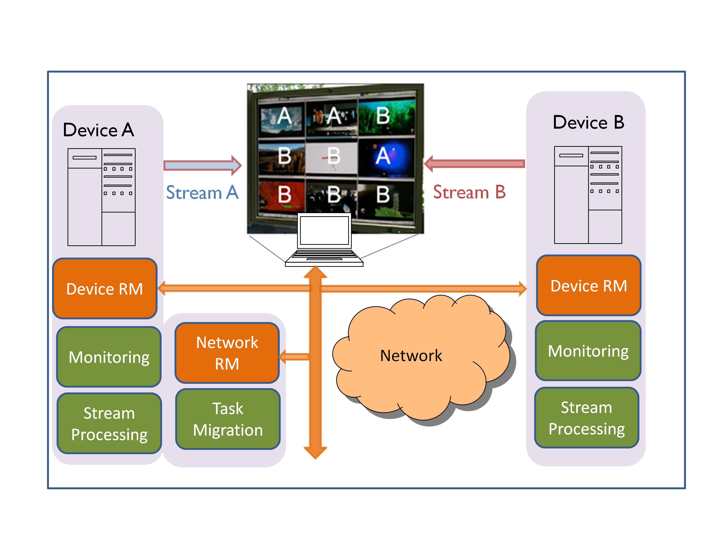
In our experiment, device A and device B both implement the decoding of video streams, followed by an image analysis function (logo-detector used for quality control) and re-encoding of the video streams (See Figure 2). Depending on the resource availability at either device, some stream processing tasks are transferred seamlessly to the less overloaded device. Finally, the output of all processed streams is sent to a display client. This task migration automatically lowers the workload at the overloaded device while all videos are visualized without any artifacts.

Load balancing at the system level involves migrating tasks between devices in the network.

We implement a Device Runtime Manager (RM) at each device that takes care of the monitoring of workload, resources, video quality, and link bandwidth within each device.Note that bandwidth monitoring is required to guarantee that the processed data can be accommodated in the available bandwidth.

While the Device RM can take care of the load balancing within the device, a Network Runtime Manager is implemented to perform the load balancing between devices in the network. To do so, it receives the monitored information from each individual Device RM and decides where, on which device, to execute each task. This way, when resources at Device A are insufficient for the existing workload the Network RM shifts some stream processing tasks from Device A to B. Obviously, this task distribution between device A and B depends on the resource availability at both devices. In our experiment the screen on the client display shows in which device each displayed video stream is currently processed. In the example in Figure 2, due to lack of resources in device A, the processing of 6 video streams has been migrated to device B while the remaining 3 have been processed on device A.

In a similar way, Figure 3 shows the monitored workload on both device A and B. Around time 65s, several stream processing tasks are added to device A, causing its overload. To decrease the load of device A the Network RM gradually shifts tasks from device A to device B resulting in the load distribution given from time 80s on. This way, load balancing between devices in the network overcomes the processing limitations of device A.

The processing load distribution over time for devices A and B.

Another way to implement load balancing between devices would be by means of down-scaling the task requirements. For video decoding applications for example, this may translate into reducing the spatial or temporal resolution of the video stream. In another experimental setup, when the workload on a decoding client becomes too high, the server transcodes the video streams to a lower resolution before sending them to the client device. This naturally reduces the workload on the device client at the cost of an increased processing at the server.

Note that we chose to place the Network RM at device A, but it could be located at any other network device as the overhead involved is very low. Note also that in both experiments the decision to migrate tasks or adapt the contents is taken to fit the processing constraints and to guarantee the desired quality-of-service.

However, another motivation for load balancing can be to minimize the energy consumption at a specific device, extending its battery lifetime, or even controlling the processors’ temperature. Think of cloud computing data centers where cooling systems are critical and account for a big fraction of the energy consumed. Load balancing between servers could be used to control the processors temperature by switching on an off processors or switching tasks between them. This could potentially reduce the cooling effort and pave the way for greener and more efficient data centers.

We are facing a future where applications are becoming increasingly complex and demanding with a highly dynamic and unpredictable workload. To tackle these challenges we require high flexibility of adaptation and cooperation from devices in the network. Our research and experimentscontribute to an environment with intelligent and flexible devices that are able to optimally exploit and share their resources and those available in the network while adapting to system dynamics such as workload, resources and bandwidth.

Is the cloud safe enough?

Wednesday, May 18th, 2011 by Robert Cravotta

The cloud and content streaming continue to grow as a connectivity mechanism for delivering applications and services. Netflix now accounts for almost 30 percent of downstream internet traffic during peak times according to Sandvine’s Global Internet Phenomena Report. Microsoft and Amazon are entering into the online storage market. But given Sony’s recent experience with the security of their PlayStation and Online Entertainment services, is the cloud safe enough, especially when new exploits are being uncovered in their network even as they bring those services back online?

When I started working, I was exposed to a subtle but powerful concept that is relevant to deciding if and when the cloud is safe enough to use, and that lesson has stayed with me ever since. One of my first jobs was supporting a computing operations group and one of their functions was managing the central printing services. Some of the printers they managed were huge impact printers that weighed many hundreds of pounds each. A senior operator explained to me that there was a way to greatly accelerate the wear and tear on these printers merely by sending a print job with the correct but completely legal sequences of text.

This opened my eyes to the fact that even when a device or system is being used “correctly,” unintended consequences can occur unless the proper safeguards are added to the design of that system. This realization has served me well in countless projects because it taught me to focus on mitigating legal but unintended operating scenarios so that these systems were robust.

An example that affects consumers more directly is exploding cell phone batteries a few years back. In some of those cases, the way the charge was delivered to the battery weakened the batteries; however, if a smarter regulator was placed between the charge input and the battery input, charge scenarios that are known to damage a battery could be isolated by the charge regulator instead of being allowed to pass through in ignorance. This is a function that adds cost and complexity to the design of the device and worse yet, does not necessarily justify an increase in the price that the buyer is willing to pay. However, the cost of allowing batteries to age prematurely or to explode is significant enough that it is possible to justify the extra cost of a smart charge regulator.

I question whether the cloud infrastructure, which is significantly more complicated than a mere stand-alone device or function, is robust enough to act as a central access point because it currently represents a single point of failure that can have huge ramifications from a single flaw, exploit, or weakness in its implementation. Do you think the cloud is safe enough to bet your product and/or company on?

Do you use any custom or in-house development tools?

Wednesday, May 11th, 2011 by Robert Cravotta

Developing embedded software differs from developing application in many ways. The most obvious difference is that there is usually no display available in embedded systems whereas most application software would be useless without a display to communicate with the user. Another difference is that it can be challenging to know whether the software for an embedded system is performing the correct functions for the right reasons or if it is performing what appear to be proper functions coincidentally. This is especially relevant to closed-loop control systems that include multiple types of sensors in the control loop, such as with fully autonomous systems.

Back when I was building fully autonomous vehicles, we had to build a lot of custom development tools because standard software development tools just did not perform the tasks we needed. Some of the system-level simulations that we used were built from the ground up. These simulations modeled the control software, rigid body mechanics, and inertial forces from actuating small rocket engines. We built a hardware-in-the-loop rig so that we could swap in and out real hardware with simulated modules so that we could verify the operation of each part of the system as well as inject faults into the system to see how it would fare. Instead of a display or monitor to provide feedback to the operator, the system used a telemetry link which allowed us to effectively instrument the code and capture the state of the system at regular points of time.

Examining the telemetry data was cumbersome due to the massive volume of data – not unlike trying to perform debugging analysis with today’s complex SOC devices. We used a custom parser to extract the various data channels that we wanted to examine together and then used a spreadsheet application to scale and manipulate the raw data and to create plots of the data that we were looking for correlations in. If I was working on a similar project today, I suspect we would still be using a lot of same types of custom tools as back then. I suspect that the market for embedded software development tools is so wide and fragmented that it is difficult for a tools company to justify creating many tools that meet the unique needs of embedded systems. Instead, there is much more money available from the application side of the software development tool market, and it seems that embedded developers must choose between figuring out how to use tools that address the needs of application software work in their project or to create and maintain their own custom tools.

In your own projects, are standard tools meeting your needs or are you using custom or in-house development tools? What kind of custom tools are you using and what problems do they help you solve?

Is the job market for embedded developers improving?

Wednesday, May 4th, 2011 by Robert Cravotta

I have an unofficial sense that there has been an uptick in the embedded market for developers. This sense is not based on hard data; rather it is based on a sense of what I hear in briefings and what types of briefings I am seeing. The message of recovery is not a new one, but over the previous year or two it felt like the undertone of the message was more of a hope than a sentiment of fact. The undertone now suggests that there may be more than just hopeful optimism to the message today.

Are you seeing more opportunities for embedded developers than the previous year or two? Is the workload growing as well as the talent being brought to bear on these projects, or are you doing more with much less? If you can provide an anecdote, please do; otherwise, use the scale below to indicate how you think the market for embedded developers is doing.

1)      The embedded market is hurting so much that improvement/growth is hard to detect.

2)      The embedded market is showing signs of revival but still has a ways to go to be healthy.

3)      The embedded market is healthy.

4)      The embedded market is growing and hiring opportunities are up.

5)      The future has never looked brighter.

6)      Other (please expand)

How do you ensure full coverage for your design/spec reviews?

Wednesday, April 27th, 2011 by Robert Cravotta

Last week I asked whether design-by-committee is ever a good idea. This week’s question derives from my experience on one of those design-by-committee projects. In this particular project, I worked on a development specification. The approval list for the specification was several dozen names long – presumably the length of the approving signatures list should provide confidence that the review and approval process was robust and good. As part of the review and approval process, I personally obtained each signature on the original document and gained some insight into some of the reasoning behind each signature.

For example, when I approached person B for their signature, I had the distinct feeling they did not have time to read the document and that they were looking at it for the first time in its current form. Now I like to think I am a competent specification author, but this was a large document, and to date, I was the only person who seemed to be aware of the entire set of requirements within the document. Well, person B looked at the document, perused the signature list, and said that person E’s signature would ensure that the appropriate requirements were good enough for approval.

When I approached person D, they took two minutes and looked at two requirements that were appropriate to their skill set and responsibility and nothing else within the specification before signing the document. When it was person E’s turn at the document, I once again felt they had not had time to look at the document before I arrived for their signature. Person E looked at the signature list and commented that it was good that person B and D had signed off, so the document should be good enough for their signature. In this example, these three signatures encompassed only two of the requirements in a thick specification.

Throughout the review and approval process, it felt like no one besides me knew all of the contents of the document. I did good work on that document, but my experience indicates that even the most skilled engineers are susceptible to small errors that can switch the meaning of a requirement and that additional sets of eyes looking over the requirements will usually uncover them during a review. Additionally, the system-level implications of each requirement can only be assessed if a reviewer is aware of the other requirements that interact with each other. The design-by-committee approach, in this case, did not provide system-level accountability for the review and approval process.

Is this lack of full coverage during a review and approval cycle a problem unique to this project or does it happen on other projects that you are aware of? What process do you use to ensure that the review process provides appropriate and full coverage of the design and specification documents?

Is design-by-committee ever the best way to do a design?

Wednesday, April 20th, 2011 by Robert Cravotta

I have participated in a number of projects that were organized and executed as a design-by-committee project. This is in contrast to most of the design projects I worked on that were the result of a development team working together to build a system. I was reminded of my experiences in these types of projects during a recent conversation about the details for the Space Shuttle replacement. The sentiment during that conversation was that the specifications for that project would produce something that no one will want once it is completed.

A common expression to illustrate what design-by-committee means is “a camel is what you get when you design a horse by committee.” I was sharing my experience with these design-by-committee projects to a friend and they asked me a good question – What is the difference between design-by-committee and a design performed by a development team? After a moment of thought my answer to that question is that each approach treats accountability among the members differently and this materially affects how system trade-offs are performed and decided.

In essence, design-by-committee could be described as design-by-consensus. Too many people in the committee have the equivalent of veto power without the appropriate level of accountability that should go with that type of power. Compounding this is that just because you can veto something does not mean that you have to come up with an alternative. Designing to a consensus seems to rely on the implied assumption that design is a process of compromises and the laws of physics are negotiable.

In contrast, in the “healthy” development team projects I worked on, different approaches fought it out in the field of trade studies and detailed critique. To an outsider, the engineering group seemed liked crazed individuals that engaged in passionate holy wars. To the members of the team, we were putting each approach through a crucible to see which one survived the best. In those cases where there was no clear “winner”, the chief project engineer had the final say over which approach the team would use – but not until everyone, even the most junior members on the team, had the chance to bring their concerns up. Ultimately, the chief project engineer was responsible for the whole system and their tie-breaker decisions were based on system level trade-offs rather than just slapping together the best of each component into a single system.

None of the design-by-committee projects that I am aware of yielded results that matched, never mind rivaled, what I think a hierarchical development team with clearly defined accountabilities would produce. Do I have a skewed perspective on this or do you know of cases when design-by-committee was the best way to pursue a project? Can you share any interesting or humorous results of design-by-committee projects that you know of? I am currently searching for an in-house cartoon we had when I worked on rockets that demonstrated the varied results you could get if you allowed one of the specialty engineering groups to dominate the design process for a rocket engine. I will share that if/once I find it. I suspect there could be analogous cartoons for any field, and I encourage you to send them to me, and I will share yours also.

Dynamic runtime task assignment

Tuesday, April 19th, 2011 by Carolina Blanch and Rogier Baert and Maja DHondt

Innovative multimedia applications – think of multi-camera surveillance or multipoint videoconferencing – are demanding both in processing power and bandwidth requirements. Moreover, a video processing workload is highly dynamic and subject to stringent real-time constraints. To process these types of applications, the trend is to use commodity hardware, because it provides higher flexibility and reduces the hardware cost. This hardware is often heterogeneous, a mix of central processing units (CPUs), graphic processing units (GPUs) and digital signal processors (DSPs).

But implementing these multimedia applications efficiently onto one or more heterogeneous processors is a challenge, especially if you also want to take into account the highly dynamic workload. State-of-the-art solutions tackle this challenge through fixed assignments of specific tasks to types of processors. However, such static assignments lack the flexibility to adapt to workload or resource variations and often lead to poor efficiency and over-dimensioning.

Another strategy would be to implement dynamic task assignment. To prove that this is feasible, we have implemented middleware that performs both run-time monitoring of workloads and resources, and runtime task assignment onto and between multiple heterogeneous processors. As platforms, we used the NVidia Quadro FX3700 and dual Intel quad core Xeon processors.

Load-balancing between the cores of a device

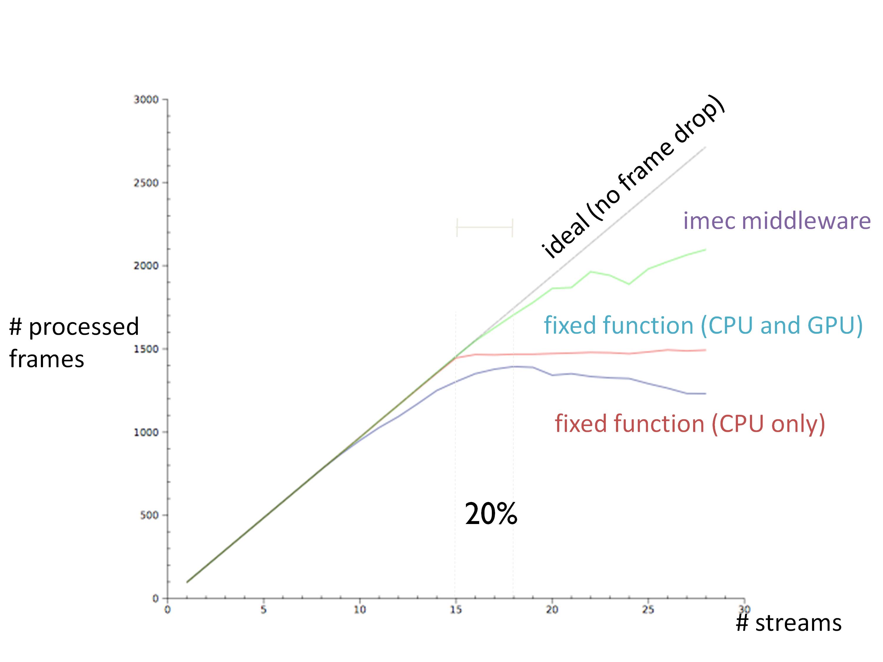
Our experiment consists of running multiple pipelines where MPEG-4 decoding, frame conversion and AVC video encoding are serialized tasks. From all these tasks, the most demanding motion estimation task, part of video encoding, can be run either on a CPU or it can be CUDA-accelerated on the GPU. Figure 1 compares our experimental runtime assignment strategy with two static assignment strategies that mimic the behavior of state-of-the-art OS-based systems.

This chart shows how the throughput increases by dynamic task assignment within a device.

The first static assignment considered consists of letting the operating system assign all tasks onto the CPU cores. The second one assigns all CUDA-accelerated tasks on the GPU while the remaining tasks are scheduled on the CPU cores. We can see how the latter one, enabling GPU-implementable versions of the most demanding tasks, increases the number of streams that can be processed from 10 to 15. However at this point, the GPU becomes the bottleneck and it limits the number of processed frames.

The last, dynamic, strategy overcomes both CPU and GPU limitations and bottlenecks by finding at runtime an optimal balance between CPU and GPU assignments. By doing so, an increased throughput of 20% is achieved in comparison with fixed assignments to GPU and CPU. This way, the efficiency and flexibility of the available hardware is increased while the overhead remains marginal, around 0.05% of the total execution time.

From the device to the cloud

Load balancing within the device is a first step that is necessary to maximize the device’s capabilities and to cope with demanding and variable workloads. But to overcome the limited processing capacity of a device, a second step is needed: load balancing at the system level. Only this will allow exploiting the potential of a highly connected environment where resources from other devices can be shared.

In addition, today’s applications tend to become more complex and demanding in both processing and bandwidth terms. On top of this, users keep demanding lighter and portable multifunctional devices where longer battery duration is desirable. Naturally, this poses serious challenges for these devices to meet the processing power required by many applications.

The way to solve this is by balancing the load between multiple devices, by offloading tasks from overloaded or processing-constrained devices to more capable ones that can process these tasks remotely. This is linked to “thin client” and “cloud computing” concepts where the limited processing resources on a device are virtually expanded by shifting processing tasks to other devices in the same network.

As an example, think of home networks or local area networks through which multiple heterogeneous devices are connected. Some of these devices are light portable devices such as I-phones and PDAs with limited processing capabilities and battery, while others are capable of higher processing such as media centers or desktops at home, or other processing nodes/servers in the network infrastructure.

One consequence from migrating tasks from lighter devices to more capable ones is that the communication and throughput between devices increases. In particular, in the case of video applications, where video is remotely decoded and transmitted, the bandwidth demand can be very high. Fortunately, upcoming wireless technologies are providing increasingly high bandwidth and connectivity enabling load balancing. This is the case of LTE femto cells where up to 100 Mbps downlink are available, or wireless HD communications systems in the 60GHz range where even 25Gbps are promised.

However, meeting the bandwidth needs is only one of the many challenges posed. Achieving efficient and flexible load balancing in the network also requires a high degree of cooperation and intelligence from devices in the network. This implies not only processing capabilities at the network side but also monitoring, decision making, and signaling capabilities.

Experimental work at imec has shown that, as challenging as it may sound, the future in which all devices in the network efficiently communicate and share resources is much closer than we think.

Is bigger and better always better?

Wednesday, April 13th, 2011 by Robert Cravotta

The collision between an Airbus A380 and a Bombardier CRJ-700 this week at John F. Kennedy International Airport in New York City reminded me of some parallels and lessons-learned when we upgraded  the target processor with a faster version. I shared one of the lessons learned from that event in an article about adding a version control inquiry into the system. A reader added that the solution we used still could suffer from a versioning mismatch and suggested that version identifications also include an automatically calculated date and time stamp of the compilation. In essence, these types of changes in our integration and checkout procedures helped mitigate several sources of human or operator error.

The A380 is currently the world’s largest passenger jet with a wingspan of 262 feet. The taxiways at JFK Airport are a standard 75-foot-wide, but this accident is not purely the result of the plane being too large as there has been an Operation Plan for handling A380s at JFK Airport that has been successfully used since the 3rd quarter of 2008. The collision between the A380 and the CRJ appears to be the result of a series of human errors stacking onto each other (similar to the version inquiry scenario). Scanning the 36-page operation plan for the A380 provides a sense of how complicated it is to manage the ground operations for these behemoths.

Was the A380 too large for the taxiway? Did the CRJ properly clear the taxiway (per the operation plan) before the A380 arrived? Did someone in the control tower make a mistake in directing those two planes to be in those spots at the same time? Should someone have been able to see what was going to happen and stopped it in time? Should the aircraft sensors have warned the pilot that a collision was imminent? Was anyone in this process less alert or distracted at the wrong time? There have been a number of air traffic controllers that were caught sleeping on the job within the last few months, with the third instance happening this week.

When you make changes to a design, especially when you add a bigger and better version of a component into the mix, it is imperative that the new component be put through regression testing to make sure there are no assumptions broken. Likewise, the change should flag an effort to ensure that the implied (or tribal knowledge) mechanisms for managing the system accommodate for the new ways that human or operator error can affect the operation of the system.

Do you have any anecdotes that highlight how a new bigger and better component required your team to change other parts of the system or procedures to mitigate new types of problems?

The battle for multi-touch

Tuesday, April 12th, 2011 by Robert Cravotta

As with most technologies used in the consumer space, they take a number of years to gestate before they mature enough and gain visibility to end users. Capacitive-based multi-touch technology burst into the consumer conscience with the introduction of the iPhone. Dozens of companies have since entered the market to provide capacitive touch technologies to support new designs and applications. The capabilities that capacitive touch technology can support, such as improved touch sensing for multiple touches, detecting and filtering unintended touches (such as palm and cheek detection), as well as supporting a stylus, continues to evolve and improve.

Capacitive touch enjoys a very strong position providing the technology for multi-touch applications; however, there are other technologies that are or will likely be vying for a larger piece of the multi-touch pie. A potential contender is the vision-based multi-touch technology found in the Microsoft Surface. However, at the moment of this writing, Microsoft has indicated that it is not focusing its effort for the pixel sense technology toward the embedded market, so it may be a few years before the technology is available to embedded developers.

The $7600 price tag for the newest Surface system may imply that the sensing technology is too expensive for embedded systems, but it is important to realize that this price point supports a usage scenario that vastly differs from a single user device. First, the Surface provides a 40 inch diagonal touch/display surface that four people can easily access and use simultaneously. Additionally, the software and processing resources contained within the system are sized to handle 50 simultaneous touch points. Shrink both of these capabilities down to a single user device and the pixel sense technology may become quite price competitive.

Vision-based multi-touch works with more than a user’s fingers; it can also detect, recognize and interact with mundane, everyday objects, such as pens, cups, paint brushes, as well as touch interface specific objects such as styli. The technology is capable, if you provide enough compute capability, to distinguish and handle touches and hovering of fingers and objects over the touch surface differently.I’m betting as the manufacturing process for the pixel sense sensors matures, the lower price points will make a compelling case for focusing development support to the embedded community.

Resistive touch technology is another multi-touch contender. It has been the work horse for touch applications for decades, but its ability (or until recently, lack of) to support multi-touch designs has been one of its significant shortcomings. One advantage that resistive touch has enjoyed over capacitive touch for single-touch applications is a lower cost point to incorporate it into a design. Over the last year or so, resistive touch has evolved to be able to support multi-touch designs by using more compute processing in the sensor to resolve the ghosting issues in earlier resistive touch implementations.

Similar to vision-based multi-touch, resistive touch is able to detect contact with any normal object because resistive touch relies on a mechanical interface. Being able to detect contact with any object provides an advantage over capacitive touch because capacitive touch sensing can only detect objects, such as a human finger or a special conductive-tipped stylus, with conductive properties that can draw current from the capacitive field when placed on or over the touch surface. Capacitive touch technology also continues to evolve, and support for thin, passive styli (with an embedded conductive tip) is improving.

Each technology offers different strengths and capabilities; however, the underlying software and embedded processors in each approach must be able to perform analogous functions in order to effectively support multi-touch applications. A necessary capability is the ability to distinguish between explicit and unintended touches. This capability requires the sensor processor and software to be able to continuously track many simultaneous touches and assign a context to each one of them. The ability to track multiple explicit touches relative to each other is necessary to be able to recognize both single- and multi-touch gestures, such as swipes and pinches. Recognizing unintended touches involves properly ignoring when the user places their palm or cheek over the touch area as well as touching the edges of the touch surface with their fingers that are gripping the device.

A differentiating capability for touch sensing is minimizing the latency between when the user makes an explicit touch and when the system responds or provides the appropriate feedback to that touch. Longer latencies can affect the user’s experience in two detrimental ways in that the collected data for the touch or gesture has poor quality or the delay in feedback confuses the user. One strategy to minimize latency is to sample or process less points when a touch (or touches) is moving; however, this risks losing track of small movements that can materially affect analyzing the user’s movement such as when writing their signature. Another strategy to accommodate tracking the movement of a touch without losing data is to allow a delay in displaying the results of the tracking. If the delay is too long though, the user may try to compensate and try to restart their movement – potentially confusing or further delaying the touch sensing algorithms. Providing more compute processing helps in both of these cases, but it also increases the cost and energy draw of the system.

While at CES, I experienced multi-touch with all three of these technologies. I was already familiar with the capabilities of capacitive touch. The overall capabilities and responsiveness of the more expensive vision-based system met my expectations; I expect the price point for vision-based sensing to continue its precipitous fall into the embedded space within the next few years. I had no experience with resistive-based multi-touch until the show. I was impressed by the demonstrations that I saw from SMK and Stantum. The Stantum demonstration was on a prototype module, and I did not even know the SMK module was a resistive based system until the rep told me. The pressure needed to activate a touch felt the same as using a capacitive touch system (however, I am not an everyday user of capacitive touch devices). As these technologies continue to increasingly overlap in their ability to detect and appropriately ignore multiple touches within a meaningful time period, their converging price points promise an interesting battle as each technology finds its place in the multi-touch market.

Is peer code inspection worthwhile?

Wednesday, April 6th, 2011 by Robert Cravotta

I am a strong believer in applying multiple sets of eyes to tasks and projects. Design reviews provide a multi-stage mechanism for bringing independent eyes into a design to improve the probability of uncovering poor assumptions or missed details. Peer performed code inspection is another mechanism to bring multiple sets of eyes to the task of implementing software code. However, given the evolution of automated code checking tools, is the manual task of inspecting a peer’s code still a worthwhile task?

Even when tools were not readily available to check a developer’s code, my personal experience involved some worthwhile and some useless code inspection efforts. In particular, the time I engaged in a useless code inspection was not so much about the code, but rather about how the team leader approach the code inspection and micromanaged the process. That specific effort left a bad taste in my mouth for overly formal and generic procedures for a task that requires specific and deep knowledge to perform well.

A staggering challenge facing code inspectors is the sheer magnitude of software that is available for inspecting. The labor for inspecting software is significant and it requires a high level of special skills and knowledge to perform. Tools that perform automated code inspections have proliferated, and they continue to improve over time, but are they good enough alternative to peer code inspections? I like Jack Ganssle’s “Guide to Code Inspections”, but even his final statement in the article (“Oddly, many of us believe this open-source mantra with religious fervor but reject it in our own work.”) suggests that the actions of software developers imply that they do not necessarily consider code inspections a worthwhile redirection of development team’s time.

Is peer-based code inspection worthwhile? Are the automated code inspection tools good enough to replace peer inspection? When is peer inspection necessary, or in what ways is automated inspection insufficient?